Single View Modeling
Overview + Major Design Choices
The main end goal of this project was to create 3D texture-mapped models from a single image using the single view modeling method. The basic steps I used are as follows:
- Image acquisition
- Calculate vanishing points
- Manually choose reference points
- Compute 3D coordinates of several points in the scene
- Define polygons based on these points
- Compute texture maps for the polygons and output them to files
- Create a 3D texture-mapped VRML model
Calculating Vanishing Points
In perspective photos (non-orthographic viewports) parallel lines will intersect at what are called vanishing points. These vanishing points can be determined by finding the intersection of 2 or more lines. For the sake of precision I will conduct it on a minimum of 3. 9 lines will be drawn on the photo (3 lines along the x axis, 3 along the y and 3 along the z axis respectively). Then this method will calculate the vanishing points in each direction from the best fit intersection between the lines.
//		This method find the best fit intersection point.
//		lines: the list of 3 or more lines to be intersected
//
SVMPoint BestFitIntersect(const std::list &lines, int imgWidth, int imgHeight)
{
  // check
  if (lines.size() < 2)
	{
	  fprintf(stderr, "Not enough lines to compute the best fit.");
	  abort();
	}

  SVMPoint bestfit;
  //iter is the pointer to the current line
  list::const_iterator iter;

  // To accumulate stuff
  typedef Matrix Matrix3;

  int numLines = (int) lines.size();
  Matrix3 A = Matrix3::Zero(numLines, 3);

  // Transformation for numerical stability

	//variables for use later:
	int vec_and_line_number = 0; //will be used to keep track of which line is currently in question
	double e1_w, e1_u, e1_v, e2_w, e2_u, e2_v;  //end points 2D homogeneous coordinates
	double a_i, b_i, c_i;

	double eigenValue;
	double eigenVector[3];
	double error_tol = 1e-10;


	/* for each line with end points e1 and e2 compute a homogenous coordinate vector representing the line
	as the cross product of its two endpointsie:		a row of A is (a_i, b_i, c_i) = e1  X  e2*/
	for (iter = lines.begin(); iter != lines.end(); iter++){
		//check that we don't have bad faulty pointers
		if (!iter->pnt1 || !iter->pnt2){
			printf("ERROR: bad pointer  in BestFitIntersection\n");
			fl_message("ERROR: bad pointer in BestFitIntersection\n");
			return bestfit;
		}
		//grab the 2D homogeneous coordinates in the image plane of both endpoints
		e1_w = iter->pnt1->w;
		e1_u = iter->pnt1->u;
		e1_v = iter->pnt1->v;
		e2_w = iter->pnt2->w;
		e2_u = iter->pnt2->u;
		e2_v = iter->pnt2->v;

		//calculate the 3 components of the cross product resultant vector
		a_i = (e1_v*e2_w) - (e1_w*e2_v);
		b_i = (e1_w*e2_u) - (e1_u - e2_w);
		c_i = (e1_u*e2_v) - (e1_v*e2_u);

		//place them into the A matrix where a row is homogeneous coordinate vector
		A(vec_and_line_number, 0) = a_i;
		A(vec_and_line_number, 1) = b_i;
		A(vec_and_line_number, 2) = c_i;

		//increment the line/vector count
		vec_and_line_number++;
	}

	//SKIPPING THE SECOND MATRIX M BECAUSE I DON'T KNOW HOW TO DO THE JACOBI STUFF
	//GOING DIRECTLY TO EIGENVAL/VECTOR OF A


	//find the eigenvector of matrix A associated with the smallest eigenvalue of matrix A
	MinEig(A, eigenValue, eigenVector);

	//2D homogeneous coordinate w in image plane
	double w = eigenVector[2];
	//check to see if w is 0...w=0 indicates the point is at infinity.
	//to account for minute variations just check that the abs(w) is less than some tiny tolerance which
	// would make w approximately 0
	if ( abs(w) <= error_tol){ //(w ~= 0)
		bestfit.u = eigenVector[0];
		bestfit.v = eigenVector[1];
		bestfit.w = eigenVector[2];
	}
	else{ //(w!=0)
		bestfit.u = eigenVector[0] / eigenVector[2];
		bestfit.v = eigenVector[1] / eigenVector[2];
		bestfit.w = 1;
	}

 return bestfit;
}
Choosing Reference Points
Computing Homography
This will compute the homogrophy of a plane specified by points a user places in the image. The idea is to estimate a homography H that maps each texture coordinate (u_i,v_i) [where u_i and v_i are between 0 and 1] to image coordinate p_i = (x_i, y_i). Normally h is the eigenvector of the 9x9 semi-positive-definite matrix whose eigenvalue is the smallest. But here it will be the eigenvector of the 2n*9 matrix where n is the number of points on the plane. I commented this method heavily so the logic should be clear.
//	Computes the homography H from the plane specified by "points" to the image plane, and its inverse Hinv.
//	The coordinate system is only converted to the plane for polygon patches where texture mapping is necessary.
//  ie: not the reference plane
void ComputeHomography(CTransform3x3 &H, CTransform3x3 &Hinv, const vector &points, vector &basisPts, bool isRefPlane)
{
  int i;
  int numPoints = (int) points.size();
  assert( numPoints >= 4 );

  basisPts.clear();
  if (isRefPlane) // reference plane
	{
	  for (i=0; i < numPoints; i++)
		{
		  Vec3d tmp = Vec3d(points[i].X, points[i].Y, points[i].W); // was Z, not W
		  basisPts.push_back(tmp);
		}
	}
  else // arbitrary polygon
	{
	  double uScale, vScale; // unused in this function
	  ConvertToPlaneCoordinate(points, basisPts, uScale, vScale);
	}

  // A: 2n x 9 matrix where n is the number of points on the plane
  int numRows = 2 * numPoints;
  const int numCols = 9;

  typedef Matrix MatrixType;
  MatrixType A = MatrixType::Zero(numRows, numCols);


/*---------------IDEA---------------------------
Want to estimate a homography H that maps each texture coordinate (u_i,v_i)
[where u_i and v_i are between 0 and 1] to image coordinate p_i = (x_i, y_i)

h is normally the eigenvector of the 9x9 semi-positive-definite matrix
whose eigenvalue is the smallest. But here it will be the eigenvector of the 2n*9 matrix
where n is the number of points on the plane.  In order to determine h (the eigenvector)
associated with the smallest eigenvalue of this matrix, we must first populate this A matrix


In single_view_modeling, the following matrix eqn

								A*h = 0
where A is a 2nx9 matrix, and h is a 9x1 vector.
When expanded, this eqn becomes...


	(	x1	y1	1	0	0	0	-x1'x1	-x1'y1	-x1')	(h00)	=	(0)
	(	0	0	0	x1	y1	1	-y1'x1	-y1'y1	-y1')	(h01)		(0)
							.				(h02)		.
							.				(h10)		.
							.				(h11)		.
	(	xn	yn	1	0	0	0	-xn'xn	-xn'yn	-xn')	(h12)		(0)
	(	0	0	0	xn	yn	1	-yn'xn	-yn'yn	-yn')	(h20)		(0)
											(h21)
											(h22)

*/

//Just need to populate A according to the matrix above... where the 1...n is denoted by i
int even_row, odd_row;
double xn, yn, xn_prime, yn_prime;

for (i = 0; i < numPoints; i++){
	even_row = 2 * i;
	odd_row = 2 * i + 1;

	xn = basisPts[i][0];
	yn = basisPts[i][1];
	xn_prime = points[i].u;
	yn_prime = points[i].v;

	//populate even rows of A ie: rows 0,2,4..2n
	A(even_row, 0) = xn;
	A(even_row, 1) = yn;
	A(even_row, 2) = 1;
	A(even_row, 3) = 0;
	A(even_row, 4) = 0;
	A(even_row, 5) = 0;
	A(even_row, 6) = -xn_prime * xn;
	A(even_row, 7) = -xn_prime * yn;
	A(even_row, 8) = -xn_prime;

	//populate the odd rows of A, ie: rows 1,3,5...2n-1
	A(odd_row, 0) = 0;
	A(odd_row, 1) = 0;
	A(odd_row, 2) = 0;
	A(odd_row, 3) = xn;
	A(odd_row, 4) = yn;
	A(odd_row, 5) = 1;
	A(odd_row, 6) = -yn_prime * xn;
	A(odd_row, 7) = -yn_prime * yn;
	A(odd_row, 8) = -yn_prime;

}

 double eval, h[9];
 MinEig(A, eval, h);

 H[0][0] = h[0];
 H[0][1] = h[1];
 H[0][2] = h[2];

 H[1][0] = h[3];
 H[1][1] = h[4];
 H[1][2] = h[5];

 H[2][0] = h[6];
 H[2][1] = h[7];
 H[2][2] = h[8];

 // compute inverse of H
 if (H.Determinant() == 0)
   fl_alert("Computed homography matrix is uninvertible \n");
 else
   Hinv = H.Inverse();

 int ii;
 printf("\nH=[\n");
 for (ii=0; ii<3; ii++)
   printf("%e\t%e\t%e;\n", H[ii][0]/H[2][2], H[ii][1]/H[2][2], H[ii][2]/H[2][2]);
 printf("]\nHinv=[\n");

 for (ii=0; ii<3; ii++)
   printf("%e\t%e\t%e;\n", Hinv[ii][0]/Hinv[2][2], Hinv[ii][1]/Hinv[2][2], Hinv[ii][2]/Hinv[2][2]);

 printf("]\n\n");
}
Converting to Plane Coordinates
This method takes a plane defined by user specified points, and converts the coordinates into a coordinate plane of the user’s choice. I commented this method heavily to outline my logic.
//		Given a plane defined by points, converts their coordinates into
//		a plane coordinate of the user's choice.
//
void ConvertToPlaneCoordinate(const vector& points, vector& basisPts, double &uScale, double &vScale)
{
	int numPoints = points.size();

	//Parameters for use later (in order of their appearance:
	Vec4d p, q, r, e_x, e_y, test_q, test_e_y, s, t, vec_from_r_to_q;
	double best_running_dp = 1.00;
	double dot_product_test, intermediate_dp;

	//Let p,q and r be 3 points in R^3. If they are not colinear, they define a unique plane.
	p = Vec4d(points[1].X, points[1].Y, points[1].Z, points[1].W);
	r = Vec4d(points[0].X, points[0].Y, points[0].Z, points[0].W);

	//want to define a coordinate system in this unique plane defined by p,q and r
	//r will be the origin of this coordinate system

	//create a base vector for the x axis of the unique plane
	//to do this, simply normalize a vector that extends from r
	e_x = p-r;
	e_x.normalize();

	/*next find the ideal q to use. The ideal q will be at such a location that e_x and e_y are orthogonal.
	To solve for this point, the dotproduct of e_x and e_y should be as close to 0 as possilbe,
	indicating they are orthogonal (90 degrees apart).*/

	/*iterate through each point and test out that point as q... remember which point yielded the the
	smallest cosine (indicating most orthogonal axis set)*/
	for (int i = 2; i < numPoints; i++){
		test_q = Vec4d(points[i].X, points[i].Y, points[i].Z, points[i].W);
		test_e_y = test_q - r;
		test_e_y.normalize();

		// Compute the
		dot_product_test = e_x[0] * test_e_y[0] + e_x[1] * test_e_y[1] + e_x[2] * test_e_y[2] + e_x[3] * test_e_y[3];
		//check if the tested q created a more orthogonal set of axis e_x and e_y, if so remember it
		if (abs(dot_product_test) < abs(best_running_dp)){
			best_running_dp = dot_product_test;
			q = test_q;
			e_y = test_e_y;
			vec_from_r_to_q = test_q - r;
		}
	}

	//decompose q-r into two components, one parallel to e_x and one othogonal to e_x
	//the parallel component is s = e_x
	//the orthogonal component is t = (q-r)-s
	//where <.,.> is the dot product of two vector

	intermediate_dp = (vec_from_r_to_q[0] * e_x[0] + vec_from_r_to_q[1] * e_x[1] + vec_from_r_to_q[2] * e_x[2] + vec_from_r_to_q[3] * e_x[3]);
	s = Vec4d(e_x[0], e_x[1], e_x[2], e_x[3]);
	//think i could just do this... s *= intermediate_dp;
	//but i'm not sure if the operator was overriden properly to do so....
	//in the meantime, a longhang works just as well.
	s[0] = s[0] * intermediate_dp;
	s[1] = s[1] * intermediate_dp;
	s[2] = s[2] * intermediate_dp;
	s[3] = s[3] * intermediate_dp;
	e_y = vec_from_r_to_q - s;
	e_y.normalize();  //t


	/*
	At this point, e_x and e_y have been calculated. They are the axis set for this new unique plane.
	Now, for any point "a" in the unique plane, its two dimensional coordinate in the plane
	w.r.t. e_x and e_y is....  ( < a-r , e_x >, < a-r , e_y > )

	Iterating through each point in the set of points, calculating its 2D coordinate in the plane, and
	keeping track of the maximum and minimum values will permit the normalization of each 2D coordinate
	by the difference between the min and max. This will yield a 2D coordinate (u_i,v_i) for each point
	p_i, where u_i and v_i are between [0,1]. Such normalized coordinates can be used as texture coordinates.
	*/
	double u_min, u_max, v_min, v_max, u, v;
	Vec4d pt_a, vec_from_r_to_a;
	Vec3d uv_Coordinate;


	u_min = DBL_MAX;
	u_max = 0.0;
	v_min = DBL_MAX;
	v_max = 0.0;

	for (int i = 0; i < numPoints; i++){
		pt_a = Vec4d(points[i].X, points[i].Y, points[i].Z, points[i].W);
		vec_from_r_to_a = r - pt_a;
		//projection onto the e_x axis (u coordinate)
		u = vec_from_r_to_a[0] * e_x[0] + vec_from_r_to_a[1] * e_x[1] + vec_from_r_to_a[2] * e_x[2] + vec_from_r_to_a[3] * e_x[3];
		//projection onto the e_y axis (v coordinate)
		v = vec_from_r_to_a[0] * e_y[0] + vec_from_r_to_a[1] * e_y[1] + vec_from_r_to_a[2] * e_y[2] + vec_from_r_to_a[3] * e_y[3];

		uv_Coordinate = Vec3d(u, v, 1.00);

		if (u < u_min){
			u_min = u;
		}
		if (v < v_min){
			v_min = v;
		}
		if (u > u_max){
			u_max = u;
		}
		if (v > v_max){
			v_max = v;
		}

		basisPts.push_back(uv_Coordinate);

	}

	//Set the u and v scales... since apparently we shouldn't store the uv coordinate normalized yet.
	uScale = u_max - u_min;
	vScale = v_max - v_min;

}
Compute 3D Positions
SameXY()
This method takes a known point and a new point both specified by the user and determines the 3D position of the specified new point with the constraint that the new point must be directly above or below the known point. This can be particularly useful when blocking out cube-like geometry. Again this method was commented heavily, so the logic is clear.
//		Computes the 3D position of newPoint using knownPoint
//		that has the same X and Y coordinate, i.e. is directly
//		below or above newPoint.
//
void ImgView::sameXY()
{
	  if (pntSelStack.size() < 2)
		{
		  fl_alert("Not enough points on the stack.");
		  return;
		}

	  SVMPoint &newPoint = *pntSelStack[pntSelStack.size() - 1];
	  SVMPoint &knownPoint = *pntSelStack[pntSelStack.size() - 2];

	  if( !knownPoint.known() )
		{
		  fl_alert("Can't compute relative values for unknown point.");
		  return;
		}

	  if( refPointOffPlane == NULL )
		{
		  fl_alert("Need to specify the reference height first.");
		  return;
		}

	//right off the bat the x and y coordinates for the new point must be the same as the known point
	//and the W coordinate will be 1.0
	newPoint.X = knownPoint.X;
	newPoint.Y = knownPoint.Y;
	newPoint.W = 1.0;
	//just need to solve for Z now...


	//matrix version of the homography for easy arithmetic operations in later parts
	Mat3d homographyMatrix = Mat3d(H[0][0], H[0][1], H[0][2], H[1][0], H[1][1], H[1][2], H[2][0], H[2][1], H[2][2]);

	double height_mag, img_cross_ratio;
	Vec3d horizon;
	/*
	There are many vectors points that will need to be defined.
	I'll define them using vectors...
	*/
	Vec3d b, r, t; //image points represented as p = [x;y;1]
	Vec3d t_0, b_0; //top and bootom of the object to be measured
	Vec3d v, t_1, v_x, v_y, v_z;

	//intermediate parameters used in calculations later...
	double r_x, r_y, t_x, t_y;
	Vec3d unconverted_b, unconverted_b_0;
	Vec3d cp_b_b0, cp_r_b, cp_v_t0;  //intermediate cross products used later
	Vec3d aa, bb, cc, dd;
	double aa_len, bb_len, cc_len, dd_len, dp_parallel_check;

	//r is the reference point off the plane, which was defined in the editor as having a reference height
	//therefore...
	r_x = refPointOffPlane->u / refPointOffPlane->w;
	r_y = refPointOffPlane->v / refPointOffPlane->w;
	r = Vec3d(r_x, r_y, 1.0);

	//t_0 is the top of the object in question
	t_x = newPoint.u / newPoint.w;
	t_y = newPoint.v / newPoint.w;
	t_0 = Vec3d(t_x, t_y, 1.0);


	//have to define v now...using the vanishing points already calculated
	v_x = Vec3d(xVanish.u, xVanish.v, xVanish.w);
	v_y = Vec3d(yVanish.u, yVanish.v, yVanish.w);
	v_z = Vec3d(zVanish.u, zVanish.v, zVanish.w);

	unconverted_b_0 = Vec3d(knownPoint.X, knownPoint.Y, 1.0);
	unconverted_b = Vec3d(refPointOffPlane->X, refPointOffPlane->Y, 1.0);

	b_0 = homographyMatrix*unconverted_b_0;
	b = homographyMatrix*unconverted_b;

	cp_b_b0 = cross(b, b_0);

	//v_x and v_y are calculated, from them it is possible to calculate the horizon.
	horizon = cross(v_x, v_y);

	//knowing the horizon and the cross product between b and b_0, it is possible to find v
	v = cross(cp_b_b0, horizon);

	//calculate t naively... don't know if this will error on a divide by 0 in a rare case.. maybe should check before
	cp_r_b = cross(r, b);
	cp_v_t0 = cross(v, t_0);
	t = cross(cp_v_t0, cp_r_b);

	//then check to make sure cp_b_b0 and the horizon are not parallel....
	//that is check to see if cross(cp_b_b0, horizon) != zeroVector
	//If v is the zero vector, the vectors were parallel and in this special case, t should be changed to just t0+b-b0
	if (v[0] == 0 && v[1] == 0 && v[2] == 0){
		t = t_0 + b - b_0;
	}

	//normalize so that in each vector the third term is 1
	/* The Following Doesn't work for some reason, so just manually entered them
		t *= t[2];
		b *= b[2];
		v_z *= v_z[2];
		r *= r[2];
	*/
	t[0] = t[0] / t[2];
	r[0] = r[0] / r[2];
	v_z[0] = v_z[0] / v_z[2];
	b[0] = b[0] / b[2];

	t[1] = t[1] / t[2];
	r[1] = r[1] / r[2];
	v_z[1] = v_z[1] / v_z[2];
	b[1] = b[1] / b[2];

	t[2] = 1.0;
	r[2] = 1.0;
	v_z[2] = 1.0;
	b[2] = 1.0;

	/*calculate the image cross ratio defined as
		H/R = ( ||t-b|| ||v_z - r|| )/( ||r - b|| ||v_z - t|| )
	*/
	aa = t - b;
	bb = v_z - r;
	cc = r - b;
	dd = v_z - t;

	aa_len = sqrt(aa*aa);
	bb_len = sqrt(bb*bb);
	cc_len = sqrt(cc*cc);
	dd_len = sqrt(dd*dd);

	img_cross_ratio = ( aa_len * bb_len ) / ( cc_len * dd_len );

	height_mag = img_cross_ratio*referenceHeight; //magnitude of the height, sign still undetermined

	/*
		At this point height_mag is the position of t0 relative to b0 in the positive direction... so
		it could actually be a negative number depending on the nature of the vector definitions. To account
		for the possibility of the vector between b0 and t0 being either parallel or anti parallel to the vector
		between the reference b and v_z, it is probably a good idea to check for anti-parallel nature and swap the sign
		so that our height is correct relative to b0.*/

	/*To check for anti-parallel and parallel, simply check the sign of the dotproduct*/
	//recall dotproduct is a1*b1+a2*b2+a3*b3, therefore...
	dp_parallel_check = (t_0 - b_0)[0] * (v_z - b)[0] + (t_0 - b_0)[1] * (v_z - b)[1] + (t_0 - b_0)[2] * (v_z - b)[2];
	if (dp_parallel_check >= 0){
		newPoint.Z = height_mag;
	}
	else{
		newPoint.Z = -height_mag;
	}

	 newPoint.known(true);

	 printf( "Calculated new coordinates for point: (%e, %e, %e)\n", newPoint.X, newPoint.Y, newPoint.Z );

	 redraw();
}
SameZPlane()
This method takes both a known and new point specified by the user and computes the 3D position of the newPoint with the constraint that the new point must have the same Z coordinate as the known point. This method has been heavily commented.
//		Compute the 3D position of newPoint using knownPoint
//		that lies on the same plane and whose 3D position is known.
void ImgView::sameZPlane()
{
  if (pntSelStack.size() < 2)
	{
	  fl_alert("Not enough points on the stack.");
	  return;
	}

  SVMPoint &newPoint = *pntSelStack[pntSelStack.size() - 1];
  SVMPoint &knownPoint = *pntSelStack[pntSelStack.size() - 2];

  if( !knownPoint.known() )
	{
	  fl_alert("Can't compute relative values for unknown point.");
	  return;
	}

//right off the bat can populate the Z and W in newPoint, but will need to calculate the X and Y
newPoint.Z = knownPoint.Z;
newPoint.W = 1.0;

//matrix version of the homography for easy arithmetic operations in later parts
Mat3d homographyMatrix = Mat3d(H[0][0], H[0][1], H[0][2], H[1][0], H[1][1], H[1][2], H[2][0], H[2][1], H[2][2]);
//matrix version of the homography inverse for easy arithmetic operations in later parts
Mat3d homographyInverseMatrix = Mat3d(Hinv[0][0], Hinv[0][1], Hinv[0][2], Hinv[1][0], Hinv[1][1], Hinv[1][2], Hinv[2][0], Hinv[2][1], Hinv[2][2]);

/*
more generalized version:
	Given reference point is t1, the new point is m0, and you want to compute the point b0
	(once you have b0, you can compute its X and Y positions using H).
	vz  can be used instead of t0 to help find b0.
	Not given the image position of b1, but can compute it from its 3D coordinates (knowing
	it has the same X-Y coords as t1 and is on the ground), using Hinv.
*/

Vec3d working_m0,	//m_0 copy... leave original m_0 untouched... not to be confused with reference point t1
	k_P,	//known Point (actual reference point t1)
	m_0,	//new point
	b_0;	//point to compute

Vec3d b_1, v, v_x, v_y, v_z, unconverted_b1;
//intermediate cross products used in calculations
Vec3d cp_working_m0_vz, cp_vx_vy, cp_b1_v, cp_working_m0_kP;


working_m0 = Vec3d(newPoint.u, newPoint.v, newPoint.w);
k_P = Vec3d(knownPoint.u, knownPoint.v, knownPoint.w);
m_0 = Vec3d(newPoint.u, newPoint.v, newPoint.w);
unconverted_b1 = Vec3d(knownPoint.X, knownPoint.Y, 1.0);
b_1 = homographyMatrix * unconverted_b1;


v_x = Vec3d(xVanish.u, xVanish.v, xVanish.w);
v_y = Vec3d(yVanish.u, yVanish.v, yVanish.w);
v_z = Vec3d(zVanish.u, zVanish.v, zVanish.w);

/*	Compute the vanishing point v	*/
cp_vx_vy = cross(v_x, v_y);//horizonatal horizon
cp_working_m0_vz = cross(working_m0, v_z);
cp_working_m0_kP = cross(working_m0, k_P);

v = cross(cp_working_m0_kP, cp_vx_vy);
/*
	A special case of is a point on the reference plane. In this case, the reference homography
	H can be used to compute its 3D position. If its not the special case, then the general case must
	be employed... as described above.
*/
if (knownPoint.Z == 0){
	b_0 = Vec3d(newPoint.u, newPoint.v, newPoint.w);
}
else{
	// as before in sameX,Y check if the cross product yielded a zero vector indicating parallelism...
	if (v[0] == 0 && v[1] == 0 && v[2] == 0){
		b_0 = cross(b_1, cp_working_m0_vz);
	}
	else{
		cp_b1_v = cross(b_1, v);
		b_0 = cross(cp_b1_v, cp_working_m0_vz);
	}
}

//normalize so that in vector b_0 the third term is 1.. again the operator wasn't working, so just did
//it out by hand.
b_0[0] = b_0[0] / b_0[2];
b_0[1] = b_0[1] / b_0[2];
b_0[2] = 1.0;

m_0 = homographyInverseMatrix*b_0;

//normalize m_0
m_0[0] = m_0[0] / m_0[2];
m_0[1] = m_0[1] / m_0[2];

newPoint.X = m_0[0];
newPoint.Y = m_0[1];

 newPoint.known(true);

 printf( "Calculated new coordinates for point: (%e, %e, %e)\n", newPoint.X, newPoint.Y, newPoint.Z );

 redraw();
}
Solving for Opposite Corners
This method takes the 2D position of two corners indicating a rectangular face and computes the opposite two corners so as to complete a rectangle in XZ plane. This is helpful for drawing walls of geometry. These method rely alot on the previously written methods sameZPlane and sameXY. Again this method is heavily commented.
//     Given the 2D positions of two corners of a rectangular face parallel to the XZ plane, compute
//     the 2D positions of the other two corners
void ImgView::solveForOppositeCorners(double u0, double v0, double u2, double v2,
									  double &u1, double &v1, double &u3, double &v3)
{
  /* Vanishing points must be known */
  assert(xVanish.known() && yVanish.known() && zVanish.known());

  // Given the 2D positions of corners p0 and p2 of the face, compute the 2D positions of p1 and p3
  // Remember that this face is on a plane perpendicular to the plane x=0
  // Store the results in variables 'u1, v1' and 'u3, v3'

//will need to use the vanishing points and construct various lines to find the points
//want to find p1 and p3 using p0 and p2


//will need some points
Vec3d p0, p1, p2, p3;	// 4 points for the corners
Vec3d v_x, v_y, v_z;	// 3 points for the vanishing points

//will need some intermediate cross products
Vec3d cp_p0_vx, cp_p0_vz, cp_p2_vx, cp_p2_vz;


//populate the known points p0 and p2
p0 = Vec3d(u0, v0, 1.0);
p2 = Vec3d(u2, v2, 1.0);

//populate the vanishing points
v_x = Vec3d(xVanish.u, xVanish.v, xVanish.w);
v_y = Vec3d(yVanish.u, yVanish.v, yVanish.w);
v_z = Vec3d(zVanish.u, zVanish.v, zVanish.w);

//calculate the intermediate cross products
cp_p0_vx = cross(p0, v_x);
cp_p0_vz = cross(p0, v_z);
cp_p2_vx = cross(p2, v_x);
cp_p2_vz = cross(p2, v_z);

//populate the unknown points p1 and p3
p1 = cross(cp_p0_vx, cp_p2_vz);
p3 = cross(cp_p0_vz, cp_p2_vx);

//Normalize p1 and p3

p1[0] = p1[0] / p1[2];
p3[0] = p3[0] / p3[2];
p1[1] = p1[1] / p1[2];
p3[1] = p3[1] / p3[2];
p1[2] = 1.0;
p3[2] = 1.0;

//report the coordinates by placing them into u1 v1 and u3 v3
u1 = p1[0];
u3 = p3[0];
v1 = p1[1];
v3 = p3[1];
}
Solve for Opposite Face
This method solves for the opposite face of a user defined rectangle.
//     Given the 2D positions of one rectangular face parallel to the XZ plane,
//     compute the 2D positions of a parallel face being swept out from it.
//     Mouse position is given; one of the lines on the parallel face should pass
//     through the mouse position
void ImgView::solveForOppositeFace(SVMSweep *sweep, double imgX, double imgY,
								   Vec3d &p4_out, Vec3d &p5_out, Vec3d &p6_out, Vec3d &p7_out)
{
  SVMPolygon *poly = sweep->poly;

  if (poly == NULL)
	return;

  // Get the four existing points
  SVMPoint *n0, *n1, *n2, *n3;
  poly->getFourPoints(&n0, &n1, &n2, &n3);

  Vec3d p0(n0->u, n0->v, n0->w);
  Vec3d p1(n1->u, n1->v, n1->w);
  Vec3d p2(n2->u, n2->v, n2->w);
  Vec3d p3(n3->u, n3->v, n3->w);

  Vec3d pMouse(imgX, imgY, 1.0);

   // Find the 2D image positions of box corners p4, p5, p6, p7, as described on the webpage.
  // You will compute these positions using the known corners of the box (p0, p1, p2, p3, defined above)
  // and the vanishing points.
  // The line through points p4 and p5 will go through the mouse position, pMouse
  // Store the results in variables p4, p5, p6, and p7.
  Vec3d p4, p5, p6, p7;

//will need some points
//Vec3d p4, p5, p6, p7	// 4 points for the corners already specified above
Vec3d v_x, v_y, v_z;	// 3 points for the vanishing points

//will need some intermediate cross products (this is basically just stacking cross products to determine points
Vec3d cp_p0_vy, cp_p1_vy, cp_p2_vy, cp_p3_vy, cp_p4_vz, cp_p5_vz, cp_pM_vx;

//populate the vanishing points
v_x = Vec3d(xVanish.u, xVanish.v, xVanish.w);
v_y = Vec3d(yVanish.u, yVanish.v, yVanish.w);
v_z = Vec3d(zVanish.u, zVanish.v, zVanish.w);

//calculate the necessary intermediate cross products
cp_p0_vy = cross(p0, v_y);
cp_p1_vy = cross(p1, v_y);
cp_p2_vy = cross(p2, v_y);
cp_p3_vy = cross(p3, v_y);
cp_p4_vz = cross(p4, v_z);
cp_p5_vz = cross(p5, v_z);
cp_pM_vx = cross(pMouse, v_x);

//populate the unknown points p4, p5, p6, p7
p4 = cross(cp_p0_vy, cp_pM_vx);
p5 = cross(cp_p1_vy, cp_pM_vx);
p6 = cross(cp_p2_vy, cp_p5_vz);
p7 = cross(cp_p3_vy, cp_p4_vz);;

 p4_out = p4;
 p5_out = p5;
 p6_out = p6;
 p7_out = p7;
}
Finding 3D positions of Box Corners
This method notes the anchor point of a box and calculates the positions of the other corners. It is heavily commented.
//    Find the 3D positions of the 8 corners of a box.  The 3D position of points[0] is known.
void ImgView::find3DPositionsBox(SVMPoint *points[8])
{
  // Computes the 3D positions of the corners of the box using their 2D positions
  // and the known 3D position of points[0].  Stores the results in points[1] through points[7].
  // Uses the sameXY and sameZ routines
  // pntSelStack is a stack of points from which one can push and pop points

//push the anchor to the stack, and keep it there since all
//pts on the bottom will be related to the anchor by sameZPlane
pntSelStack.push_back(points[0]);

/*Calculate the locations of the lower 4 points first
	assume anchor is the bottom front corner as shown in pic*/

/* -------LEFT BOTTOM POINT ---------*/
//first push the left bottom point to the stack
pntSelStack.push_back(points[4]);
//we know it is in the same ground plane, so can use sameZplane .
sameZPlane();
//be sure to pop if off before moving on to the next point
pntSelStack.pop_back();

/* -------RIGHT BOTTOM POINT ---------*/
pntSelStack.push_back(points[1]);
sameZPlane();
pntSelStack.pop_back();

/* -------REAR BOTTOM POINT ---------*/
pntSelStack.push_back(points[5]);
sameZPlane();
pntSelStack.pop_back();


/*Calculate the locations of the upper 4 points second
	assume anchor is the bottom front corner as shown in pic

Find each upper coordinate by simple taking each point on the bottom
level and finding the coordinate directly above it (in the sameXY)
*/


/* -------FRONT UPPER POINT (directly above anchor 0) ---------*/
pntSelStack.push_back(points[3]);
//since this point is directly above the anchor, can use sameXY
sameXY();
pntSelStack.pop_back();
pntSelStack.pop_back(); //don't want to be holding the anchor anymore, so finally pop it off too

/* -------REAR UPPER POINT (directly above pt5) ---------*/
pntSelStack.push_back(points[5]);
pntSelStack.push_back(points[6]);
sameXY();
pntSelStack.pop_back();
pntSelStack.pop_back();

/* -------LEFT UPPER POINT (directly above pt4) ---------*/
pntSelStack.push_back(points[4]);
pntSelStack.push_back(points[7]);
sameXY();
pntSelStack.pop_back();
pntSelStack.pop_back();

/* -------RIGHT UPPER POINT (directly above pt2) ---------*/
pntSelStack.push_back(points[1]);
pntSelStack.push_back(points[2]);
sameXY();
pntSelStack.pop_back();
pntSelStack.pop_back();
}
Computing Camera Position and Projection Matrix
This method computes the position of the camera, assuming the reference homography and reference height have already been specified. It uses a simple concept that the camera must project through the image plane and onto the ground plane. A vertical ray will define this intersection. Uses sameZplane() function written previously to help easily find the X and Y coordinates. I have not tested this function yet… but jotted out the logic of the code.
// Compute the camera position
void ImgView::computeCameraParameters()
{
  if (refPointOffPlane == NULL) {
	fl_message("Reference height must be set\n");
	return;
  }

  if (!homographyComputed) {
	fl_message("Must first compute reference homography\n");
	return;
  }

  // Computes the height of the camera, store in z_cam, and then x and y coordinates of the camera,
  // storing in x_cam and y_cam
  double z_cam = 0.0;
  double x_cam = 0.0, y_cam = 0.0;

/*
c0 will project onto the image plane at a location defined by the intersection of the ray
from c0 through the camera center with the image plane. This ray will be vertical, extending directly
up from the ground plane through the image plane and through the camera center. Because this ray can
be infinitely long, it will have the same projection as the Z vanishing point v_z. Using v_z in combination
with the sameZplane function will give the X and Y coordinate of the camera
*/


//will need a homography matrix in easy arithmetic friendly form...
Mat3d homographyMatrix = Mat3d(H[0][0], H[0][1], H[0][2], H[1][0], H[1][1], H[1][2], H[2][0], H[2][1], H[2][2]);

//vanishing point and its components
Vec3d v, v_x, v_y, v_z;

//horizon
Vec3d pre_horizon;

//image points represented as p = [x;y;1]
Vec3d r;
double x_comp, y_comp;
//intermediate points
Vec3d unconverted_ref_pt, converted_ref_pt;
//svm points for use later
SVMPoint horizon_svmPt, refPt_svm, c0;

//intermediate cross products
Vec3d cp_vx_vy, cp_r_convREF;

//convert the ref point
unconverted_ref_pt = Vec3d(refPointOffPlane->X, refPointOffPlane->Y, 1.0);
converted_ref_pt = homographyMatrix*unconverted_ref_pt;

//determine the image points
x_comp = refPointOffPlane->u / refPointOffPlane->w;
y_comp = refPointOffPlane->v / refPointOffPlane->w;
r = Vec3d(x_comp, y_comp, 1.0);


//populate vanishing points v_x, v_y and v_z
v_x = Vec3d(xVanish.u, xVanish.v, xVanish.w);
v_y = Vec3d(yVanish.u, yVanish.v, yVanish.w);
v_z = Vec3d(zVanish.u, zVanish.v, zVanish.w);

//calculate the intermediate cross products
cp_vx_vy = cross(v_x, v_y);
cp_r_convREF = cross(r, converted_ref_pt);


pre_horizon = cross(cp_vx_vy, cp_r_convREF);

//normalize pre_horizon and converted ref pt and v_z
pre_horizon[0] = pre_horizon[0] / pre_horizon[2];
converted_ref_pt[0] = converted_ref_pt[0] / converted_ref_pt[2];
v_z[0] = v_z[0] / v_z[2];
pre_horizon[1] = pre_horizon[1] / pre_horizon[2];
converted_ref_pt[1] = converted_ref_pt[1] / converted_ref_pt[2];
v_z[1] = v_z[1] / v_z[2];

//populate horizon_svmPt
horizon_svmPt.u = pre_horizon[0];
horizon_svmPt.v = pre_horizon[1];
horizon_svmPt.w = 1.0;
horizon_svmPt.W = 1.0;

refPt_svm.u = converted_ref_pt[0];
refPt_svm.v = converted_ref_pt[1];
refPt_svm.w = 1.0;
refPt_svm.X = refPointOffPlane->X;
refPt_svm.Y = refPointOffPlane->Y;
refPt_svm.Z = 0.0;
refPt_svm.W = 1.0;
refPt_svm.known(true);

c0.u = v_z[0];
c0.v = v_z[1];
c0.w = 1.0;

//use the refPt_svm to determine the correct height/ z coordinate of the camera position
pntSelStack.push_back(&refPt_svm);
pntSelStack.push_back(&horizon_svmPt);
sameXY();
pntSelStack.pop_back();

//use the refPt_svm to determine the correct x and y coordinate for the camera position
pntSelStack.push_back(&c0);
sameZPlane();
pntSelStack.pop_back();
pntSelStack.pop_back();

//remember to get the height/z coordinate from the horizon_svmPt and the x and y from c0
z_cam = horizon_svmPt.Z;
x_cam = c0.X;
y_cam = c0.Y;

 camPos[0] = x_cam;
 camPos[1] = y_cam;
 camPos[2] = z_cam;

 printf("Camera is at [ %0.3f %0.3f %0.3f ]\n", camPos[0], camPos[1], camPos[2]);

 camComputed = true;
}
Testing
How I built models
I adopted the following pipeline when building 3d texture mapped models from a single image…
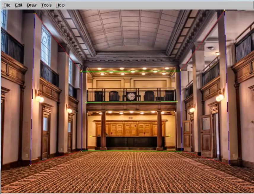
- Draw 3 lines for each axis on long lines in the scene aligned with axis.
- Calculate VPs
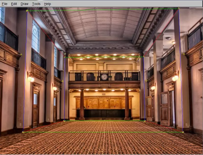
- Connect 4 of the lines to make a rectangle (if they shared vertices).
- Manually enter the values of the 4 lower points.
- Manually enter the value of 1 upper point and mark as ref
- Compute Homography
- Use sameXY and sameZplane to specify the coordiante of the rest of the points in a box.
- Create polygons out of each side of the box and name them.
- Export as the wrl file type, not vrml
- Use Irfan view to batch convert all the exported .tga files to .gif
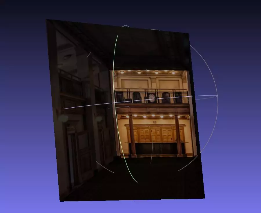
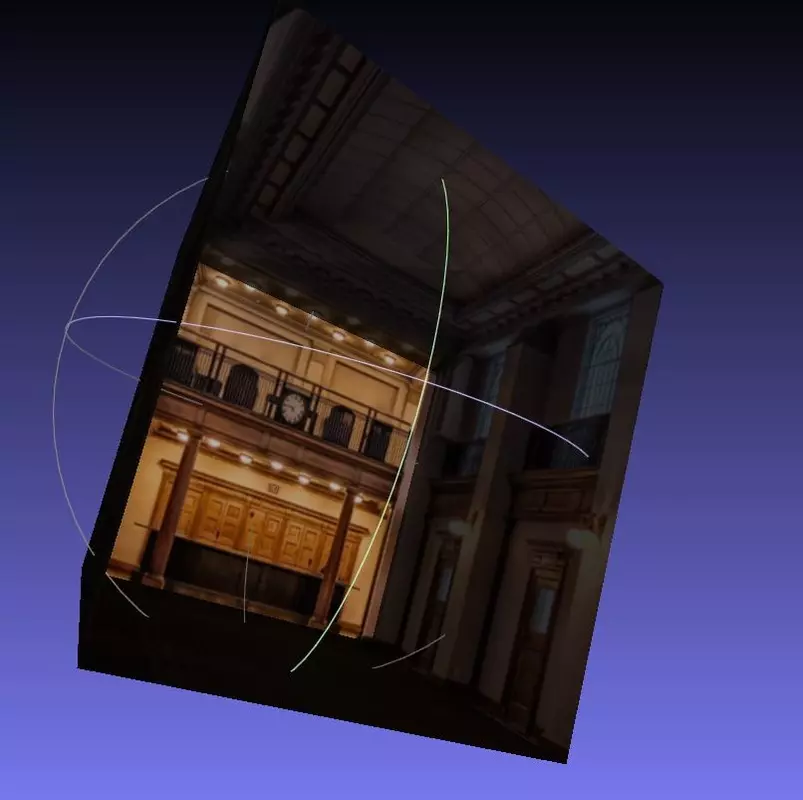
- Import the mesh (.wrl) file into meshlab using the import option
- Look around at the cool model
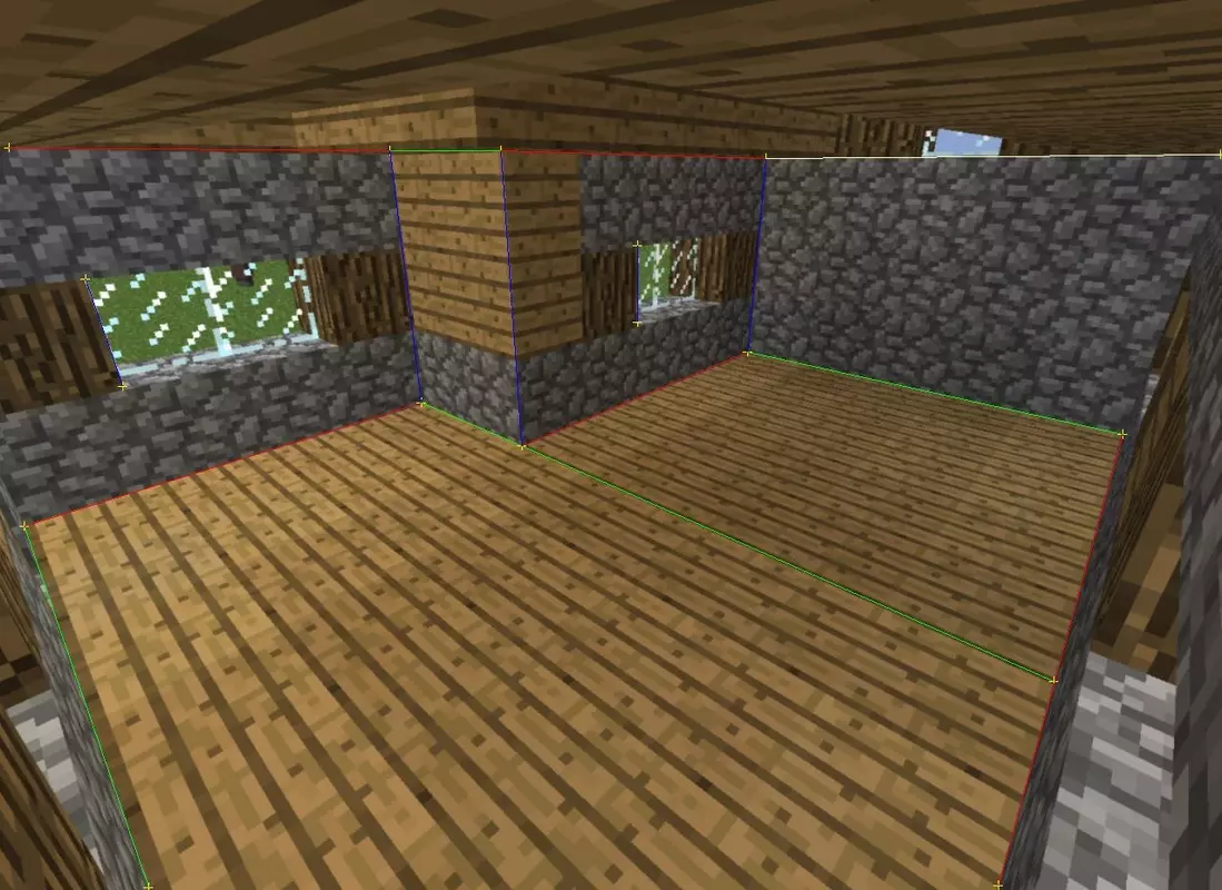
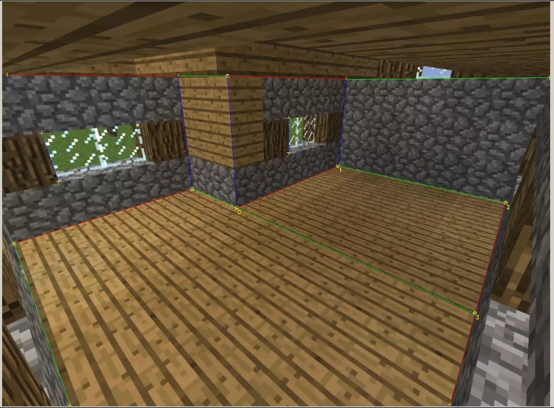
A few pictures from this pipeline using a very simple source image are shown below.





Comments