Fiducial Marker Tracking for Augmented Reality
![]()
Introduction
Augmented reality is a hot topic today (2016). As consumer products begin to emerge for VR & AR, and as mobile devices become more powerful, various applications will follow. There are endless industry motivations for augmenting a view of the real world with virtual elements. Real time overlays for entertainment, video games, education, text translation (signs), highlighting obstacles, robot navigation and many more applications are beginning to morph from research topics into marketable products. A shared need among all augmented reality systems is the maintenance of an accurate estimation for the relationship between virtual and real worlds. More specifically the knowledge of camera pose should be robustly tracked.
The goal of this project was to implement a real time tracking system for determining object or camera pose for augmented reality applications. An ideal implementation would manage to reconstruct 3D geometry from the real world. However, for real-time applications this is computationally difficult. More often markers are used (be it artificial or natural) and their movement is tracked frame to frame to yield information regarding the pose of the camera.
A lot of current AR systems are trying to leverage natural features as markers. This is called Natural Feature Tracking (NFT). In NFT, point and region features are automatically or even adaptively detected for robust tracking. The benefits of NFT over artificial markers include reducing the geo-graphical limitations on tracked area, reducing the likelihood of losing visible features, and maintaining control over the selection of desirable features for various criterion. While these are meaningful benefits especially in extrapolating AR beyond a controlled environment, implementing a stable NFT system is notably more difficult than a system which uses artificial markers. The process of tracking artificial markers is commonly referred to as Fiducial Marker Tracking because it relies upon intentionally placed and easily detectable artificial features (fiducials). The position of at least 3 such fiducials in each frame can yield a viewing pose relative to the features.
This project implements fiducial marker tracking in order to estimate the pose of an object relative to a webcam as well the pose of the webcam relative to the fiducial marker. Tracking is limited to a single marker or rigid collection of markers known as a “board”. With the knowledge of either marker pose, or camera pose relative to an assumed fixed marker, modern game engines are used to overlay geometry on the video feed.
Approach
Outline
- Integrate OpenCV with a modern game engine.
- Generate physical fiducial markers.
- Detect marker in each frame of a webcam feed.
- Estimate pose of marker.
- Estimate pose of camera.
- Communicate pose information to Game Engine.
- Use video stream as rendered background in the virtual scene.
- Update virtual objects in game engine using pose information.
- Use the estimated camera pose to control the pose of the virtual camera.
Integrate OpenCV w/ Modern Game Engine
There are a few popular game engines currently available. Specifically Unreal Engine 4 and Unity 5 were explored in this project. In hindsight, Unity is highly recommended for this project in particular given native support for Quaternion based transformations and easier customization of depth based rendering.
Integrating OpenCV with Epic’s Unreal Engine 4 was attempted. The Aruco Module from the OpenCV extra contributor modules was also required for this project and thus required integration as well. There are two options for integrating OpenCV with UE4. The first option involves an OpenCV plugin for UE4 that includes pre-built binaries and performs the library linking. This is the easiest option, but does not contain any of the extra contrib modules. The plugin is available here: https://drive.google.com/file/d/0B95oaUYR7VMWN3E0aDRLaHVvMms/view. The second option is to create OpenCV static libraries (including any necessary contrib modules) and link them using the Unreal Build System. This is significantly more involved, but likely necessary for the Aruco Module. The generation of static libraries for OpenCV and the Aruco module was attempted for this project but enormous roadblocks were encountered due to conflicting namespaces between OpenCV and the libraries in UE4. Additionally some of the containers used in OpenCV and Aruco were not properly handled by the custom garbage collection system in UE4. Overall this approach proved futile.
Integrating OpenCV with the Unity game engine requires the use of a paid OpenCV plugin, available here: https://www.assetstore.unity3d.com/en/#!/content/21088. However, this suffers from the lack of any necessary contrib modules as well. The plugin was not used for this project.
Because the integration of OpenCV (including the proper modules) using either engine proved cumbersome, an alternative approach was adopted. The final approach was to write an external program in raw C++ to handle all of the tracking using OpenCV and Aruco. The external program then communicates pose information to the game engine.
Create Physical Fiducial Markers
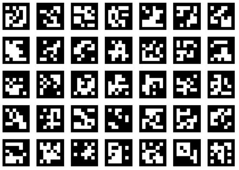
A fiducial marker is an artifical marker intended for tracking. The Aruco module was used to generate fiducial markers to print on card stock. Aruco markers were chosen for their easy generation and internal codification. The Aruco marker is a square marker with an inner binary matrix. See the figure below for examples of Aruco markers.
![]()
A black border means the marker can be detected quickly, while the binary code provides a means of verifying and more importantly identifying the marker. Marker identification is important in the Perspective N-Point problem where markers serve as tracking points and an identification yields an easy link between 2d projected points and their known 3D locations in the body frame. One marker is sufficient to estimate a pose using the 4 corners as tracking points, however a board of markers arranged in a plane yields a more robust set of tracking points. The Aruco module provides dictionaries of fiducial markers: http://docs.opencv.org/3.1.0/d5/d0b/classcv_1_1aruco_1_1Dictionary.html#gsc.tab=0 .
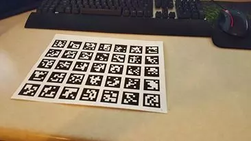
A program was written to generate an evenly spaced 5x7 grid of Aruco markers using a predefined dictionary of markers. The grid was saved to an image file and printed onto physical paper.
Detect marker in each frame of a webcam feed
The next challenge is detecting the markers. Aruco provides helpful tools to assist in the process and an easy means of tuning the many parameters that dictate performance. However, it is important to understand whats going on in the big scheme of things. The general process can be broken into two stages: Detecting Candidates and Verifying Candidates. To detect marker candidates, an adaptive threshold is used to segment the black squares that define the Aruco marker. After segmentation, contours are extracted. Any contours that would not indicate a square, ie: that are concave, are eliminated here. To verify the candidates, each is checked for the internal codification. The program is given a dictionary of valid markers to search for, and if the checked code exists in the dictionary the marker candidate is accepted. The process of checking the internal codification involves applying a perspective transform to the candidates to yield the marker in a canonical form where the bits can be extracted via a thresholding.
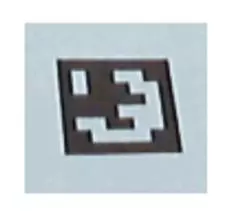
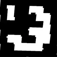
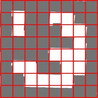
The images above depict the process of candidate verification. From left to right:
- Detected Candidate
- Apply Perspective transform to yield canonical form
- Threshold to extract codification bits.
This process is performed each and every frame in order determine the 2D coordinates of marker corners in the frame.
Estimate pose of marker
Estimating the marker pose relative to the camera is essentially a Perspective N-Point Problem. The problem is to determine a rigid body transform from identified (labeled), observed features on a rigid body knowing the coordinates of the features in the body’s frame. The “n” 3D points in the body’s frame are already known because the board was generated with a known spacing and all points are coplanar. The detected corresponding 2D projections in the image are the detected corners found previously.
A Perspective N-Point problem can be broken into a set of equations and solved with enough examples. Too few examples, and the Degrees of Freedom (DOF) cannot be eliminated. For example, a P2P problem corresponds to observing two features in the image and results in four constraints. Each constraint eliminates two DOFs resulting in only two remaining DOFs. If instead n = 3 (P3P) then zero DOFs remain, but isolated point solutions are still possible (ie: multiple solutions exist). One can visualize this as trying to position a triangle in a pyramid formed by rays extending from the camera center. To achieve a truly unique solution, 6 points are required… however this is not always necessary in practice. Some of the multiple solutions can be eliminated under prior knowledge, real world limitations, or poses from previous frames etc. A common implementation is iterative PNP which strongly considers the estimated pose form the previous frame.
![]()
OpenCV provides a PnP algorithm, in normal, RANSAC and iterative forms. Given the tracked object is an Aruco board which yields many points for robust detection, there is no need for RANSAC. If instead, natural features were being detected, then RANSAC PnP would be a much better option to remove the effects of outliers. Estimating pose with Aruco works well using just the generic PnP provided by OpenCV.
The PnP algorithm requires camera intrinsics and distortion coefficients from a calibrated camera. This was my first time calibrating a camera. A program was written to calibrate the webcam using a generated Charuco board. This involved generating a Charuco board image, printing it out, and taking photos from various angles. A Charuco board is a chess pattern board with Aruco markers in the white spaces. The Charuco board was used because it is easier and arguably more robust than a chess board.
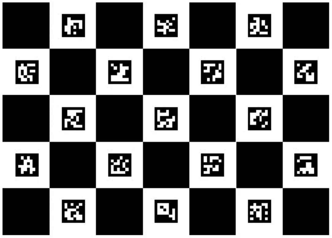
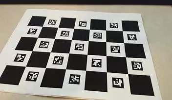
Estimate Pose of Camera
The estimation of pose using Aruco and OpenCV PnP will yield an estimated pose of the marker with respect to the camera. For some applications, the pose of camera in the world frame is desired. This can be obtained by assuming the marker is stationary and back-solving to get pose of camera relative to the marker.
In reality this proves rather difficult as the various programs use different orientation encoding and different coordinate systems (mixed left and right handed), none of which are well defined. The first approach was to convert the orientation of the marker from the custom encoded axis angle (magnitude stores angle) used by OpenCV and Aruco to a normal rotation matrix. This function helps: http://docs.opencv.org/3.1.0/d9/d0c/group__calib3d.html#ga61585db663d9da06b68e70cfbf6a1eac. Then the rotation matrix is inverted and used to rotate the translation component of the marker’s pose relative to the camera. The product is negated to yield the translation of the camera relative to the marker. Together the inverted rotation and the new translation are stored in a new transformation matrix to describe the pose of the camera relative to the marker.
Communicate Pose Information to Game Engine
Recall that the final approach involved an external program for all tracking related tasks. The pose information must still be communicated to the Game Engine. After a great deal of experimentation with TCP (Client + Server setup) networking was put aside in favor of a functional intermediate file writer. The external program writes the pose to a temporary file which is parsed in the game engine of choice. Careful consideration was given to conflicting files reads/writes and file size. Files never contain more than a few frames of data before being overwritten, to avoid long parse times. Additionally the pose information is kept short. Transformation matrices for camera pose are flattened into vectors dropping the last row for a total of 12 values per pose. For marker pose, an axis angle representation is used where the axis is a 3 element vector and the angle is encoded as the magnitude of that axis. In both cases, a custom parser translates all the pose information into a useful format for the game engine. This involves a lot of jockeying with coordinate systems to yield functional results. Again, given the poorly documented nature of the various coordinate systems and orientation formats, occasionally a straight focused math approach is less productive than a bit of trial and error.
In the case of Unreal Engine 4, the engine does not fully support quaternion based orientations nor does it expose transformation matrix functionality to the user. Remarkably, the very modern engine forces a programmer to go through hurdles to use anything but Euler Angle based orientation formats. While this may be fine for FPS style videogames, anything involving elaborate movement in 6DOF suffers terribly. After days of debugging and multiple solutions involving reauthoring a fair portion of engine code, implementing quaternion libraries and transformation matrix formats in UE4, the engine was dropped in favor of Unity for its native support of Quaternion based orientations.
Use video stream as rendered background in the virtual scene
Ideally the video stream could be used as a background over which all geometry is rendered. Unfortunately this is not easily achieved in Unreal. Perhaps easier implementations exist in Unity. However, Unreal provides a means for creating dynamic materials that can be applied to billboards, along with a means of updating the textures used in the material. This method is helpful: https://docs.unrealengine.com/latest/INT/API/Runtime/Engine/Engine/UTexture2D/UpdateTextureRegions/index.html. The billboard can use a dynamic material, and the texture for that material can be updated with the frame data from the webcam video source (read frame by frame via OpenCV integrated in Unreal).
Then this billboard can be locked to a fixed relative position in front of the camera. Objects located between the billboard and the camera will effectively appear to be in front of a video background, but if they drop behind the billboard they are occluded. Some custom render depth buffers or special post processing tricks could be implemented to keep the objects visible even if they move behind the billboard. Alternatively, the objects could stay at a fixed distance from the camera and their scale could change to simulate the distance changing but this option was not explored.
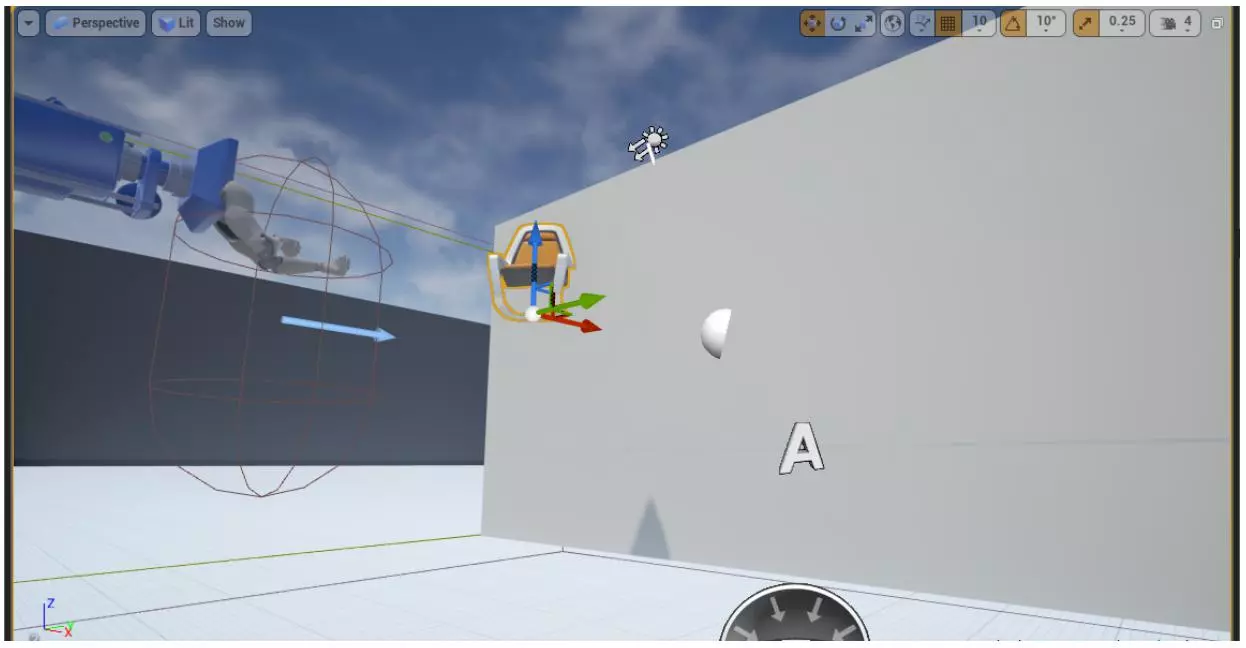
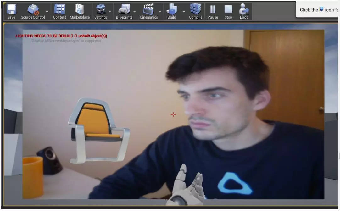
Various implementations of the dynamic textures, in game material and billboards were implemented in Unreal Engine, including a dynamic texture that was updated directly from captured frame data during image capture using OpenCV integrated in UE4. But recall that the final implementation involved using an external program to handle all tracking related tasks. Unfortunately there was an unexpected hurdle to overcome when combining the webcam billboard background with the external program: OpenCV (and also the webcam) does not support multiple programs accessing the webcam simultaneously. After a great deal of debugging and attempted fixes, no proper solution was found. Instead the final approach involved another workaround where frames (image data) are written to intermediate image files and read at runtime to update dynamic textures. Again special care was taken to avoid conflicts in read/write access.
A similar setup was implemented in Unity. A billboard was generated and fixed in front of the camera. At runtime the dynmaic texture is updated from intermediate image files stored by the external program which captures frames.
Update virtual objects in game engine using pose information
When using the pose of the physical virtual marker relative to the camera, the virtual object should be position relatives to the virtual camera. The custom parsers written for each game engine extract the pose information. They then augment the pose information according to the different coordinate systems used in each engine. Here the left-right hand coordinate system conversions and coordinate system orientations are taken into consideration. The pose of the virtual objects are then updated with each new updated webcam frame (these come less frequently than rendered frames). The pose of the virtual object is interpolated between its current orientation and the parsed pose. This keeps movement smooth. The end result is a pairing between the virtual object pose and the physical marker pose. The object appears to sit atop the marker in the image even when it is moved.
While unity uses a quaternion based system to encode orientations of virtual objects, Unreal uses an archaic system defined by euler angles. The engine does not fully support quaternion based orientations nor does it expose transformation matrix functionality to the user. As mentioned previously, a great dela of time was invested into attempted solutions involving reauthoring a fair portion of engine code, and implementing quaternion libraries and transformation matrix formats in UE4. However the internal updates of transformations was too deep into the engine code to eliminate completely and the resulting projects all ended in some form of gimbal lock. Unreal was dropped in favor of Unity for its native support of Quaternion based orientations, and the gimbal lock issues were eliminated.
Update pose of the virtual camera
For some applications, it is desirable to have the virtual camera move to match the estimated pose of the physical camera relative to the physical marker. The estimation of camera world pose was covered previously, and updating it is as simple as leaving the virtual subject/object at the world center and updating the virtual camera pose to match the estimated camera pose. All considerations from the previous section regarding pose/orientation formats apply here.
Results
Installing OpenCV
After a great deal of trial and error, OpenCV was compiled from source and test projects were built with OpenCV using Visual Studio 2015 Community. The contributor modules were also compiled including the Aruco module and a few demo projects from the module were successfully built to verify that things are working. The entire process took an astonishing amount of time… ~10 hours debugging faulty installations and compilations.
Integrating OpenCV with UE4
The prebuilt UE4 plugin and used to successfully integrate standard OpenCV with UE4. Testing this was accomplished by using OpenCV to create a dynamic webcam material.
![]()
As mentioned in the approach, manually compiled OpenCV w/ additional modules (Aruco) was attempted but did not cooperate with Unreal Engine due to conflicting name spaces and incompatible containers for garbage collection. An external program was written instead and the information was communicated to the game engine. This process was used for unity as well.
Marker Detection and Pose Estimation
The results of marker detection are shown below. The black square defining each marker is clearly outlined and the marker ID from the used dictionary is overlaid.
![]()
Pose estimation of the marker relative to the camera works well, even for partially occluded boards. The image below shows this well as the board is partially blocked by a hand.
![]()
Translating to Game Engine
The intermediate file writers and file parsers were a success for both the pose information and the frame image data. While this required significantly more code, and is cumbersome of setup and launch, the results are nearly identical to those achievable by an internal OpenCV integration.
As mentioned previously, a great deal of effort was expended attempting to solve gimbal lock issues inherent to Unreal Engine’s orientation formats. The pose estimation worked well until orientation were reached that produced gimbal lock. Avoiding these orientations intentionally resulted in better behavior, but when moving the camera by hand it was difficult to maintain precise control of the orientation.
The issues resulting from gimbal lock were resolved in unity which supports quaternion based orientations. A video of the realtime results:
Screen captures from that video:
![]()
![]()
![]()
![]()
![]()
Discussion and Conclusions
In the end the project yielded working results, but not without an unreasonable amount of jockeying. It seemed that every implemented solution to an encountered obstacle resulted in the exposure of a new complication that rendered the implemented solution irrelevant. The project may have been overwhelmingly frustrating and unexpectedly time intensive for the meager results it produced, but a great deal of learning occurred in the process.
I am now confident in using an industry standard toolset (OpenCV), including building it from source and prototyping applications. I’ve learned a great deal about detecting markers and about designing markers for robust detection. I’ve learned how to calibrate a camera. I’ve learned a great deal about the Perspective N-Point problem which is incredibly important to the tracking problems in a field that is very interesting to me (Virtual Reality). SideNote: Many popular virtual reality headsets are visually tracked using infrared LEDs identified by their strobe pattern or frequency. I have also learned a great deal about transformation geometry representations and manipulations including quaternion and rotation matrix encoding as well as stacked reference frames. Not quite as relevant to the computer vision field, I’ve also learned quite a bit about two different popular game engines.
Overall the results in Ue4 proved less than ideal due to seemingly unavoidable gimbal lock. The results from Unity were much cleaner. It is clear that when dealing with poses that make full use of their 6DOF, a more robust encoding is necessary for orientation. Quaternion or axis angle representations work well here.
Although it was functional, I was not happy with the implemented solutions for communicating pose information and frame image data. Ideally the systems would be self contained without the need for an external application, or at the very least information would be communicated more elegantly with a networked solution. I was disappointed I could not get either to work.
The better results from Unity also show a small amount of error in the position of the virtual object even when its orientation is accurately updated. I believe the reason for this is that the estimated translation is based off the real-world spacing of the board image used for the marker. The image was generated with an intended spacing in mind and this was noted and provided as input to the implemented tracking program. However, when printing the image on paper I used a print setting to fit the image to the page rather than leave it unscaled. The result was a slight difference in actual spacing. A more accurately printed board should alleviate those issues.
If I were to extend the project further, I’d like to implement some form of natural feature tracking with a RANSAC version of the PNP algorithm.



Comments