Custom Beer Pong Tables
I’ve always enjoyed building things, but rarely get to share my creations. The obvious solution is to choose a project that’s intrinsically designed for a party. So the custom beer pong tables were born. While I don’t really care that much for beer pong myself, I have enjoyed building tables. They started off simple but as always when finishing up a project, there’s a strong itch to build a better version with new ideas. Although the first tables were just sturdy carpentry projects, 2 tables were taken a step further to party greatness, which I dubbed v1.0, and v2.0.
Table v1.0
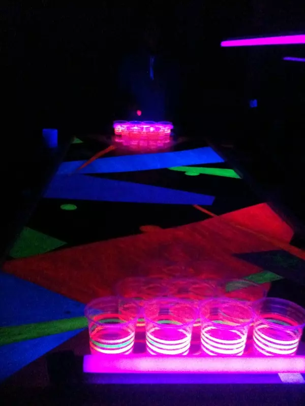
I designed the first table to be portable, fold-able and lightweight. Decorating the table was accomplished with black lights and fluorescent paint. But the glowing effects didn’t cut it… v2.0 needed some powered electrical light sources.

Table v2.0
v2.0 was meant to be an exercise in electrical engineering. The design was ambitious and inspired by quite a few electrical projects floating around the web. One open source project in particular really made this possible.
Specs:
- Automatic ball washers
- Center LED matrix/grid
- Bluetooth connectivity
- Frequency spectrum analyzer synced with music being played on a laptop displayed on the center matrix.
- Scrolling Text Display
- Photoresistor triggered LED rings around the cups.
Building the Physical Table (Wood Work)
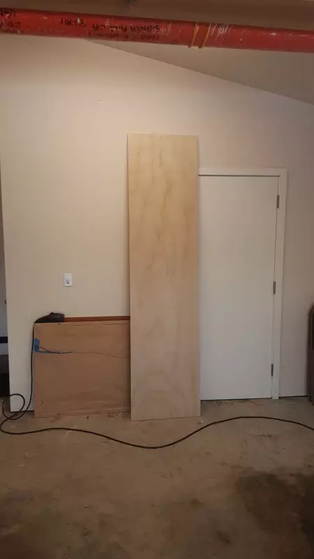
The new table requires a lot of electronic components. The table is to be subjected to rowdy party goers, potential party fouls and spilled beverages. This means that to properly house all these components a more substantial frame had to be constructed. I opted to use wood materials again, but witnessing some significant warping in the first table I chose to use heavy duty ply and build a more rigid frame.
Constructing the Frame Rails


Assembling the Frame


Drawing the Outline for the LED Grid on the Upper Lid


Countersinking Holes for the LED Grid on the Upper Lid


Cutting Support Rails for the Acrylic to Sit Above the Upper Lid


Drilling holes for the Connectors on the Ends of the Table


Priming the Table with Spray Can Sealer/Primer


Laying Out the Electronics


Assembling 20 PCBs for the Cups


Creating the center LED Grid
I used enamel coated wire to connect hundreds of LEDs. The wire was wrapped snuggly around the leads to connect the cathodes and anodes of rows and columns. The enamel coating was then melted away during soldering, and proper connections were tested for each lead. This took a LONG time. If I were to do it again I’d definitely figure out a way to use a few LED strips. That way they could be RGB as well.


Securing the Acrylic Support Risers

Adding the Automated Ball Washers


Assembling and Testing all the Electronic Components


Comments