
Bathymetry Coffee Table - Data Driven Design
I’ve been intrigued by furniture design lately, and decided to take a stab at making a custom coffee table based on bathymetry data of the San Francisco bay. Build log is below!
Initial design
August, 2019
The idea for this table started with a strong desire to experiment with pouring epoxy/resin. Most of the existing resin pour projects I’ve seen are “river” tables, where resin is poured into a single channel between two pieces of wood. While I find these tables intriguing, I wanted the subject of the pour to be data driven. I decided I’d do a pour outlining the SF bay! Additionally, I started planning around concrete instead of wood, as it should better match my industrial loft.
Get the bathymetry data!
August, 2019
I want this piece to be engaging, and invite curiosity. And if someone stares into the resin, I’d like their curiosity to be rewarded with actual information about the shape of the bay floor. So rather than freehand this piece, I’ll leverage actual scan data. I turned to historic bathymetry data from NOAA.
Generating contour maps from bathymetry data
The first obstacle was generating quantized depth contours that I could import into a CAD program. I started by writing some software to accomplish the following…
- Ingest NOAA bathymetry data (or alterntively any geoTIFF bathymetry data)
- Visualize depth maps
- Segment depth maps into clusters and visualize
- Quantize depth maps into discrete tiers
- Automate the interpretation of polygonal contours for each tier
- Automate the creation of a CAD model from contours
I have provided all my source code here: github.com/dcyoung/coffee-table
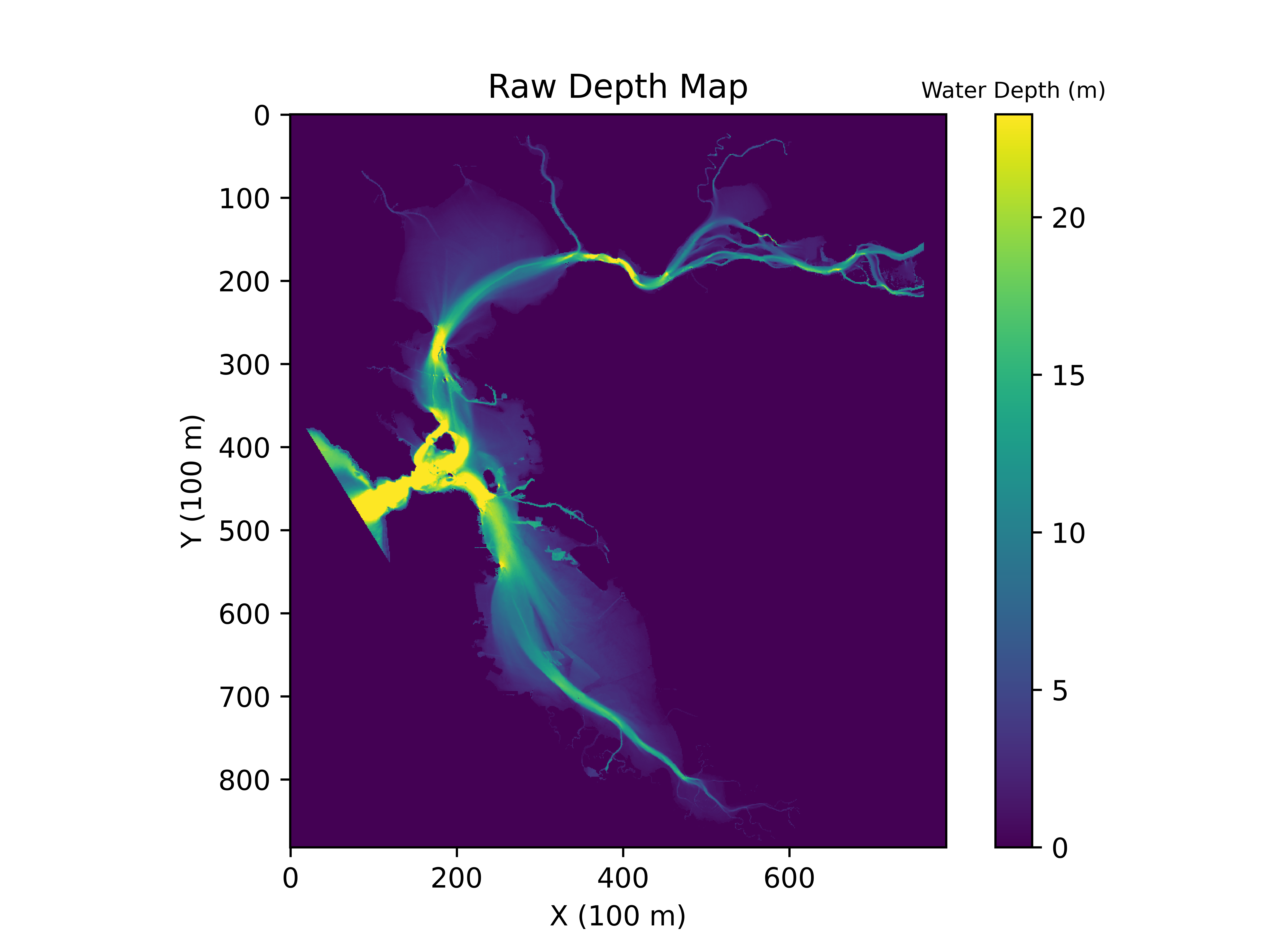
Visualizing Raw Bathymetry Data
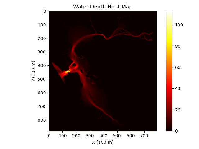
The easiest way to visualize the data is as a depth-map (inverse of a height map) where color represents the depth of the water.
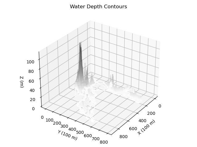
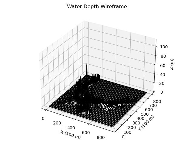
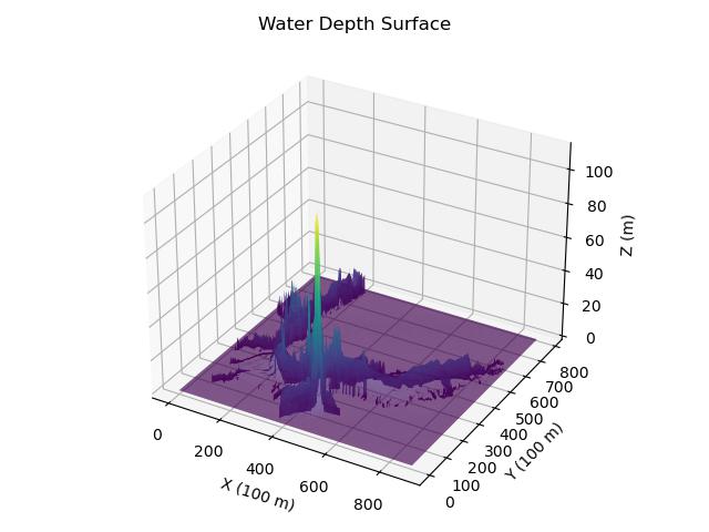
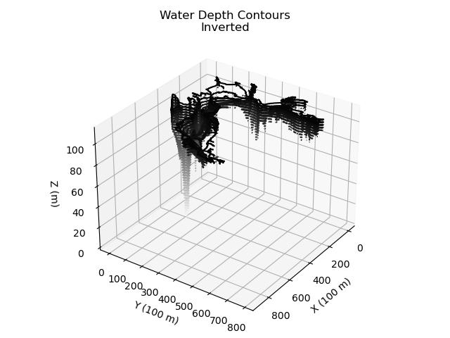
The same data can also be represented in a number of 3 dimensional plot (shown below).
| contour | wireframe | surface | contour (inverted) | wireframe (inverted) | surface (inverted) |
|---|---|---|---|---|---|
 |
 |
 |
 |
 |
 |
Quantizing Bathymetry Data
The distribution of depth values is not uniform. Plotting the depth data values as a histogram shows how the absolute range of depth values far exceeds the range of the majority of depth measurements. That is to say, there are outliers, where depth changes dramatically in a very small region. This can be seen in the yellow section of the heatmap above - near the golden gate bridge.
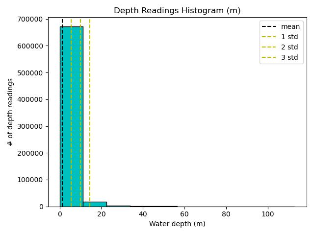
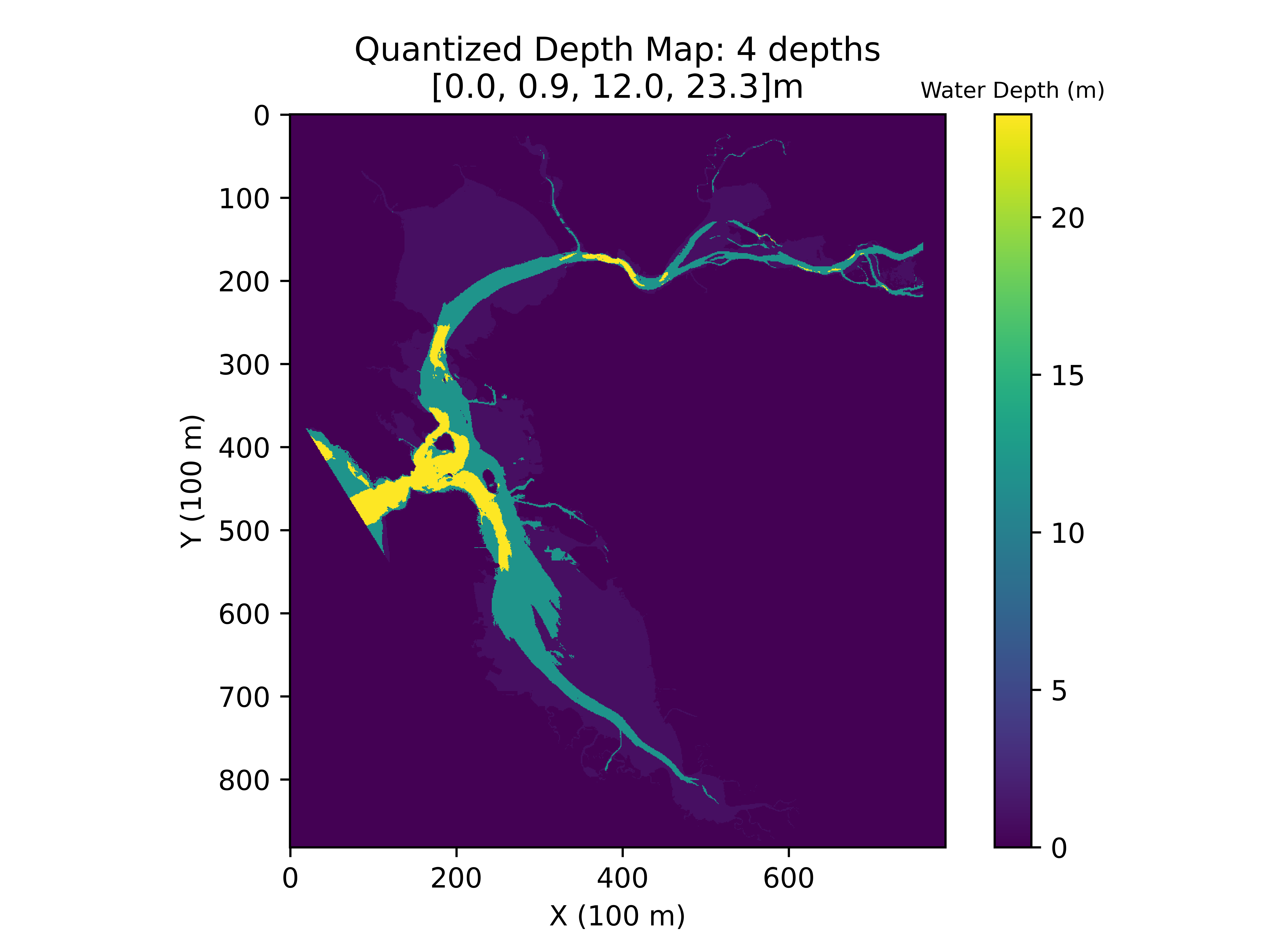
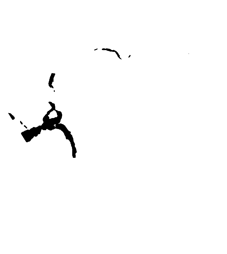
In order to create more meaningful contours, the depth data is clipped (outliers removed) and quantized to better smooth the raw data for the purposes of this project. My code produces quantized depth maps in the form of colored images - with each depth contour corresponding to a single color.

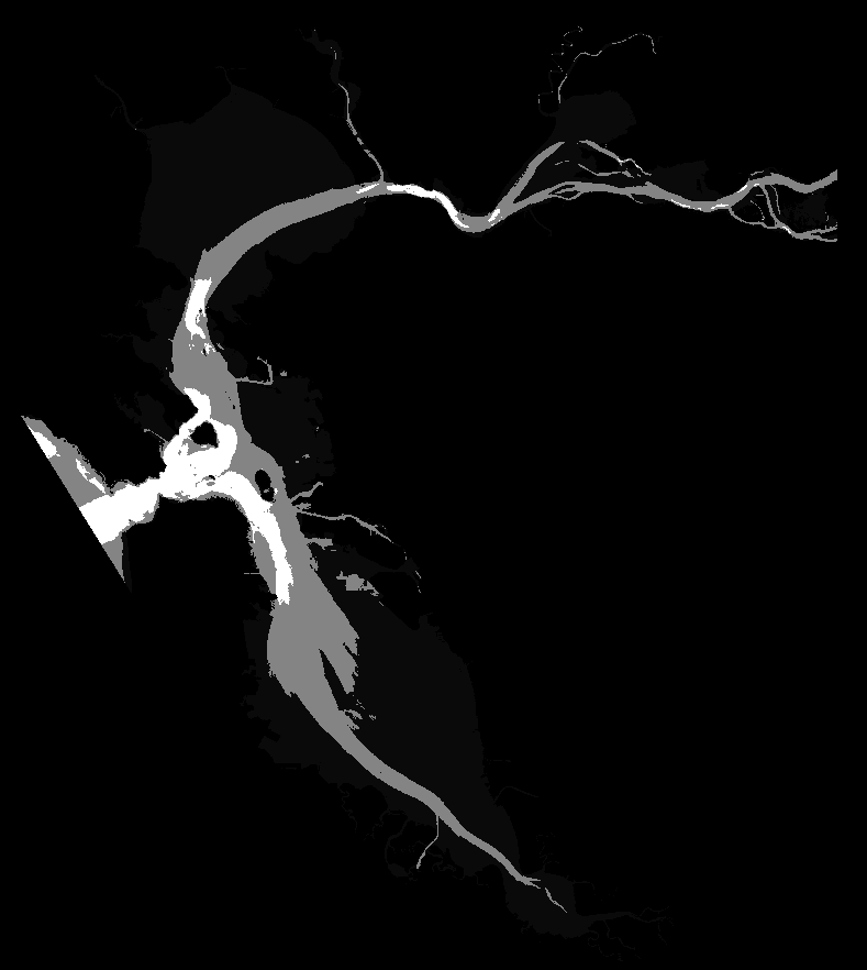
Once I have quantized the data, I apply some smoothing logic to reduce image noise and export both a binary mask and polygonal data for each contour. This data can be used to as templates for a laser cutter or to autogenerate the CAD models.
Shown below are the produced binary maps for a few quantized layers, before and after smoothing.
| . | Layer 0 | Layer 1 | Layer 2 |
|---|---|---|---|
| Before Smoothing | 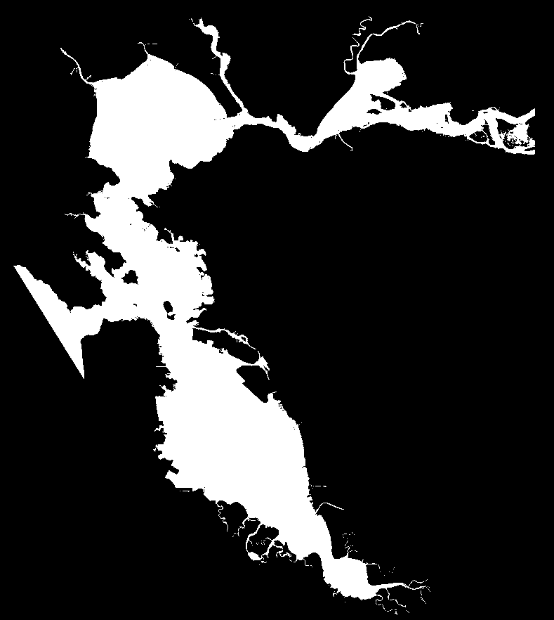 |
 |
 |
| After Smoothing |  |
 |
 |
3D Pre-Viz
With the contours above its also possible to get an early visual of the bathymetry in the form of a 3D mesh. I used THREE.js to quickly generate meshes in an interactive visual. I have a preview (using a different model of lake tahoe) available here: https://dcyoung.github.io/coffee-table/.
CAD Modeling
October, 2019
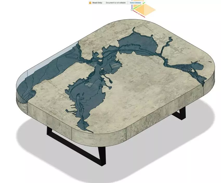
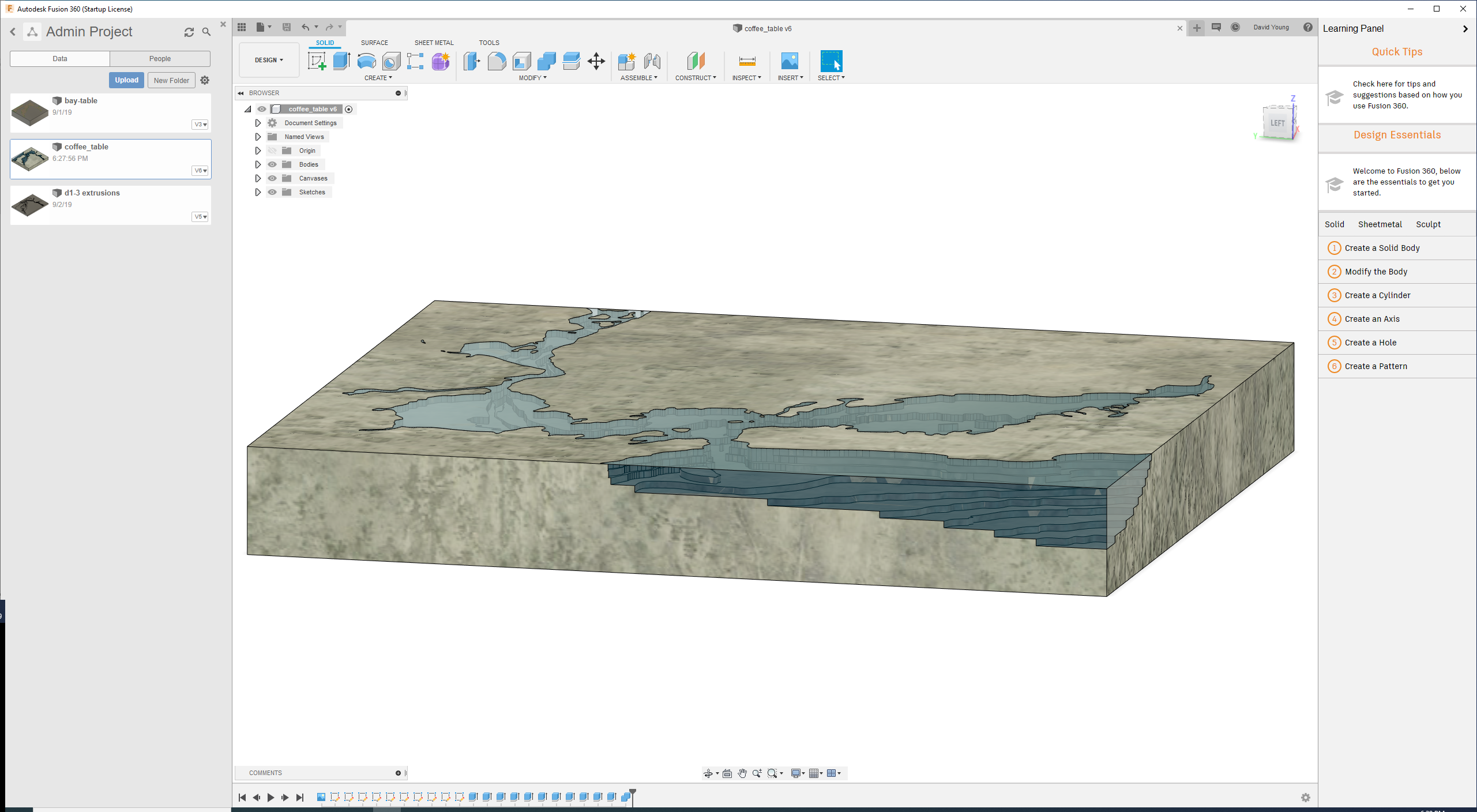
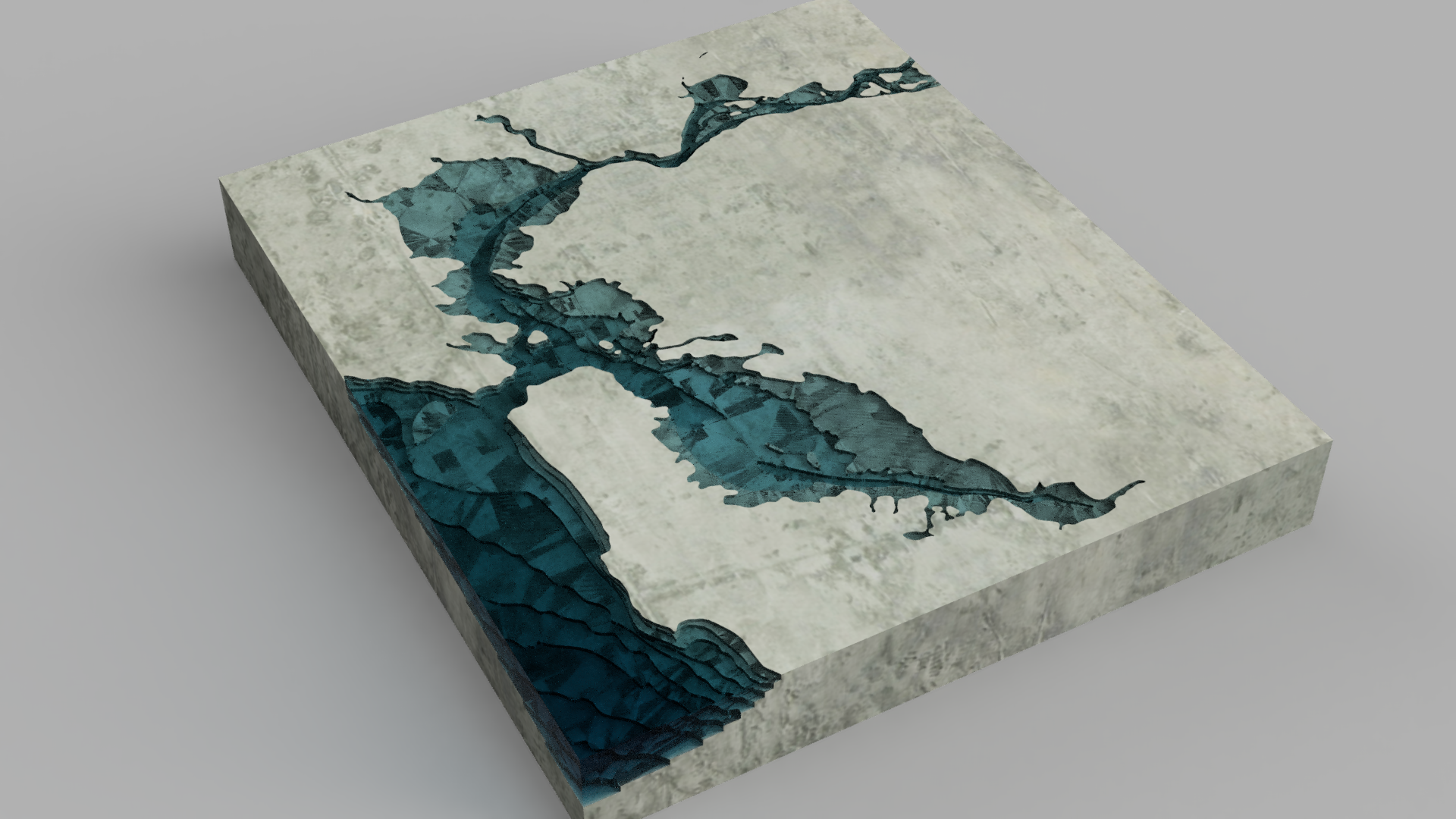
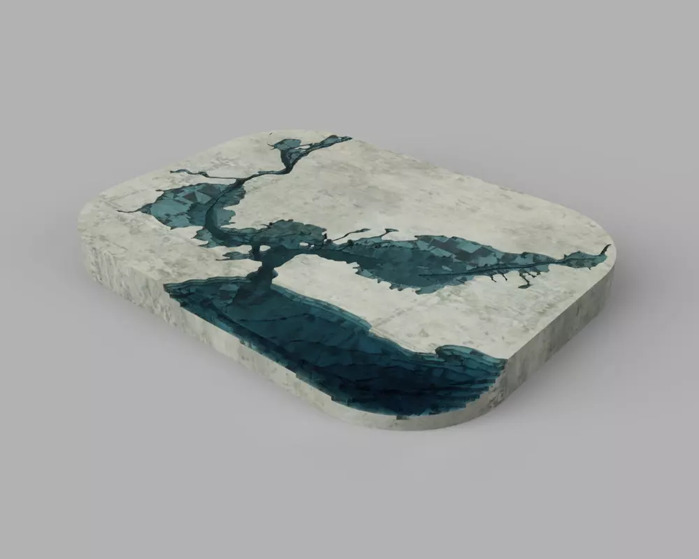
Using Fusion360, I modeled a few versions of the table, before landing on the right shape and size.
| Cad Render | Cad Render |
|---|---|
 |
 |
 |
 |
 |
 |
|
 |
 |
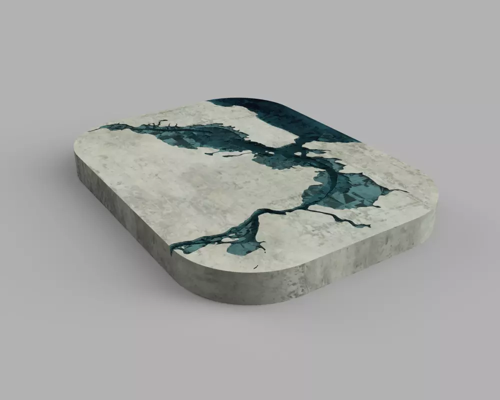 |
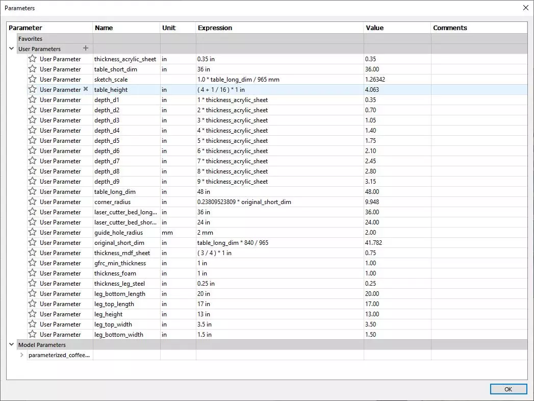
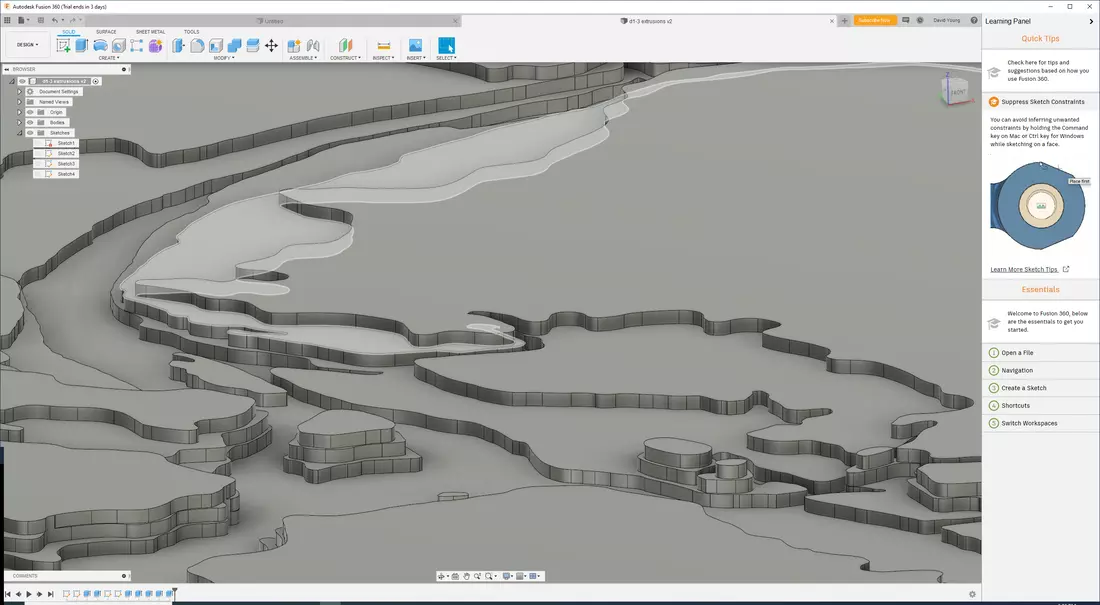
I parameterized the model to allow for easy adjustments of critical values or material properties. Fusion360 also has a programmatic API, which I leveraged to automatically generate geometry from the contour data produced by earlier scripts. This meant I could iterate on the data processing and see the final CAD results almost instantly. I’ve provided these scripts here: github.com/dcyoung/coffee-table/tree/master/fusion360
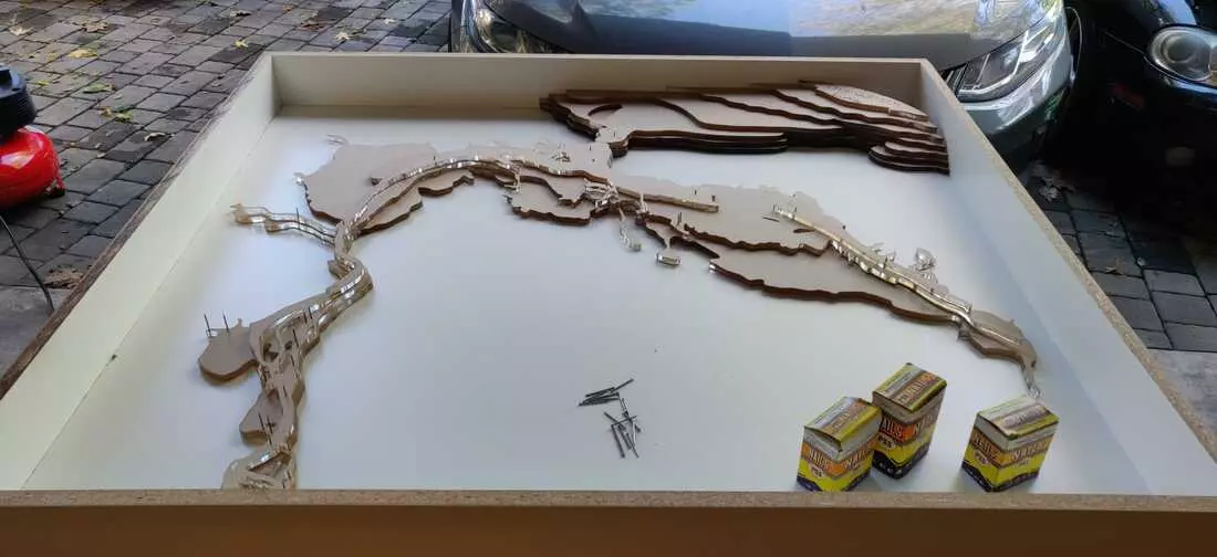
Laser Cutting Acrylic
November, 2019
Recent travel has kept me from working on the table, but I did manage to create some templates for the laser cutting machine. To save material and cost, I “nested” (efficiently arranged) all the parts to be cut. Jumping between different programs, I was stunned to find poor support and standardization for mechanical drawing formats. A few programs even failed to detect units in a clean .dxf file, and many others preferred SVGs. I would have expected a much cleaner and more efficient workflow for something so common. Nevertheless, I was able to make all parts fit within a half sheet of acrylic, without introducing too many subdivisions. While a more efficient layout could have been achieved, it would mean splitting more pieces and working out a method for align them at mold time. I settled on a nice balance.

Laser cutting the acrylic went smoothly and the parts look beautiful!
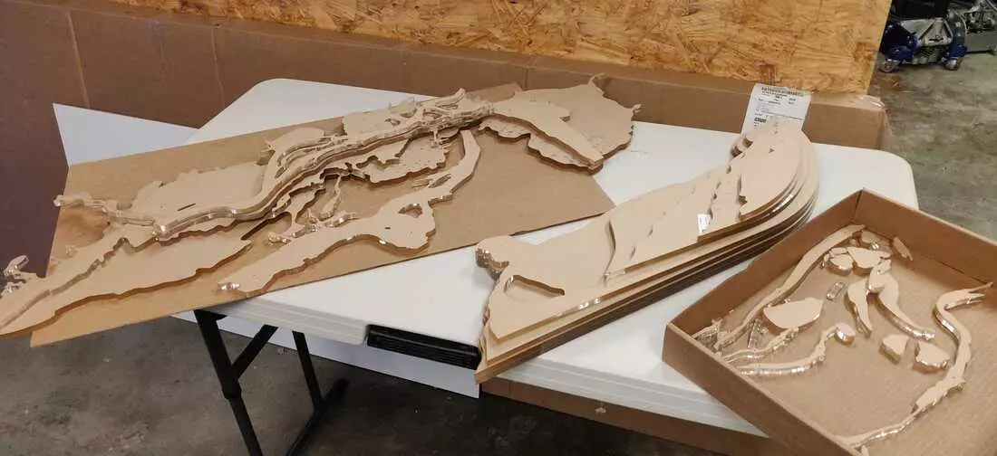
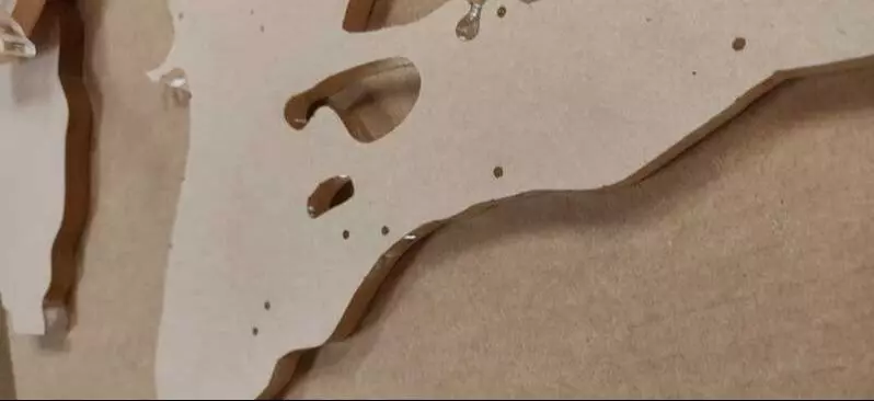
I was sure to add some guide-holes to the templates before laser cutting which should help align the pieces.
Building the Concrete Mold
December, 2019
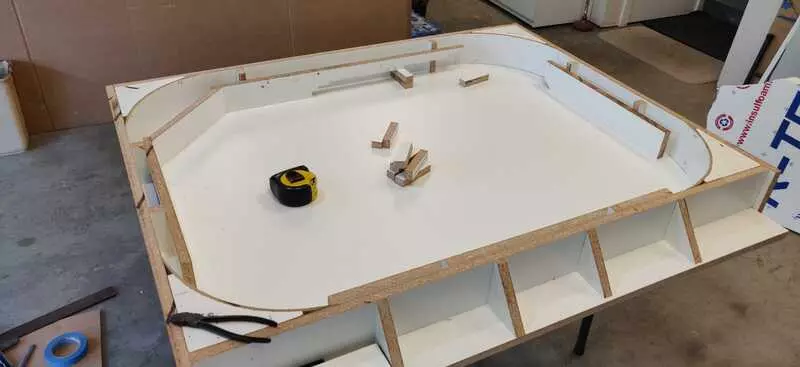
The next step was building the concrete mold. I started by creating an MDF box.
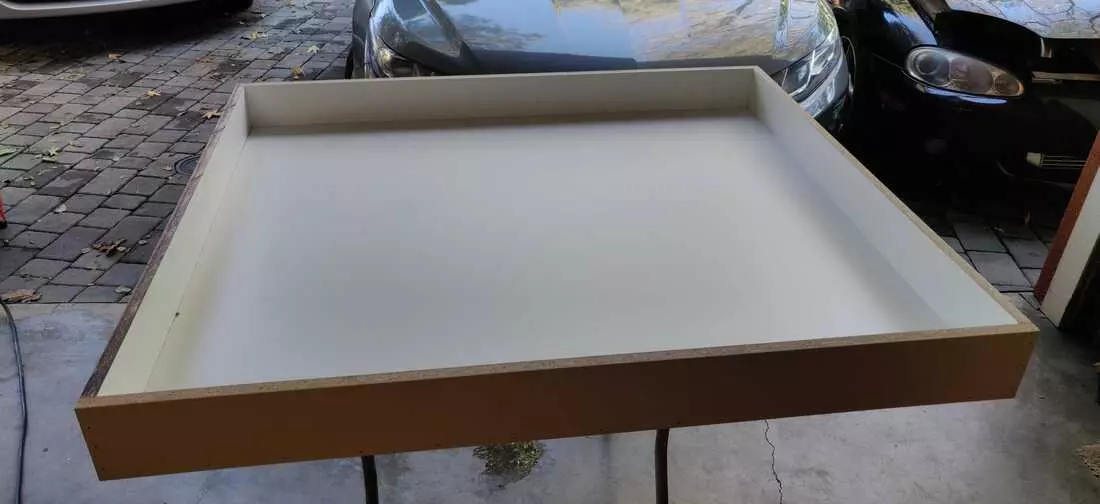
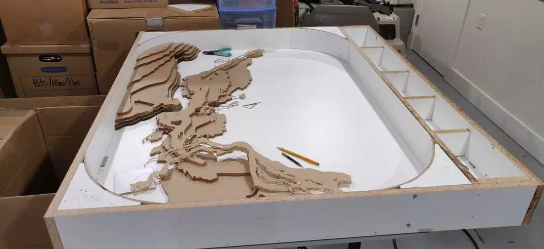
I created rounded inserts for the curved corners of the table. I used a thin MDF skin and wet the back of the wood to make it more pliable.
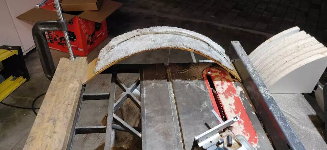
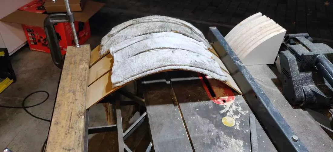
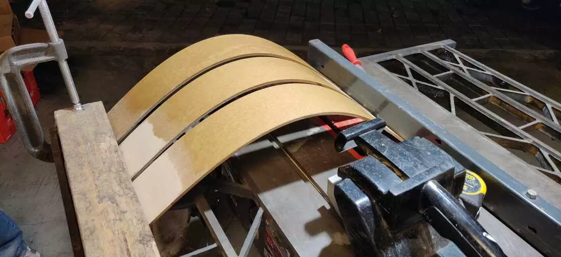
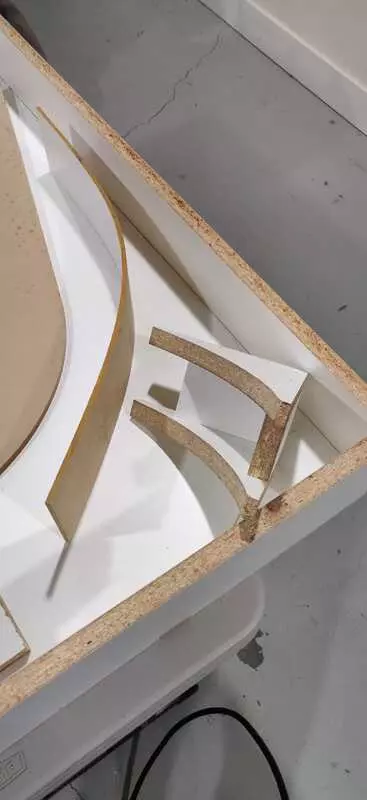
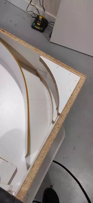
The frame of the mold turned out pretty well.
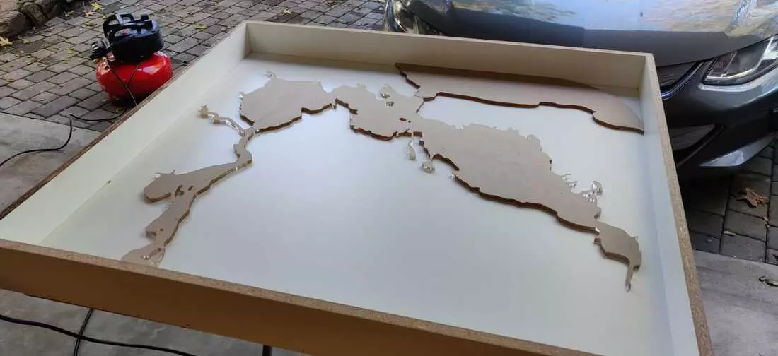
Unfortunately, seeing the frame in person made my realize the table just seemed too large (48x42”). I decided to shorten the dimensions a bit (48x36”). Luckily this only took ~5min thanks to the previous work I’d done to parameterize the CAD model. Adjusting the physical dimensions was easy as well. I simply inserted and reinforced a new wall in the existing mold.
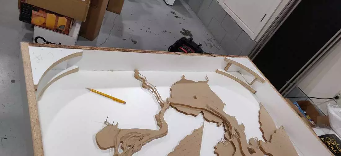
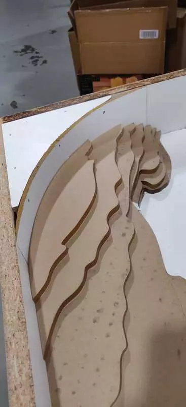
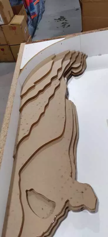
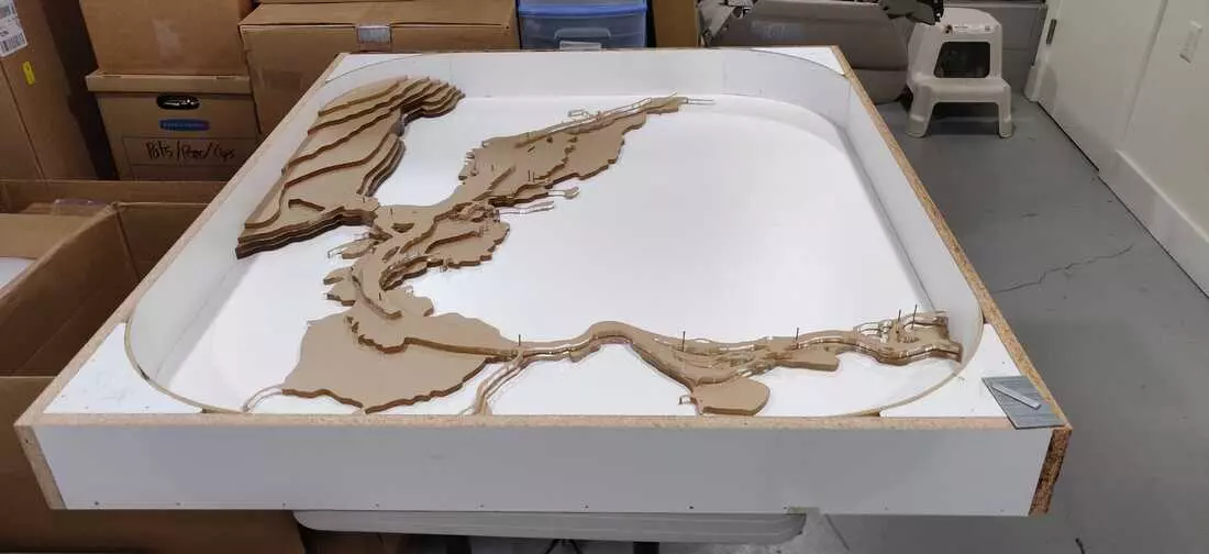
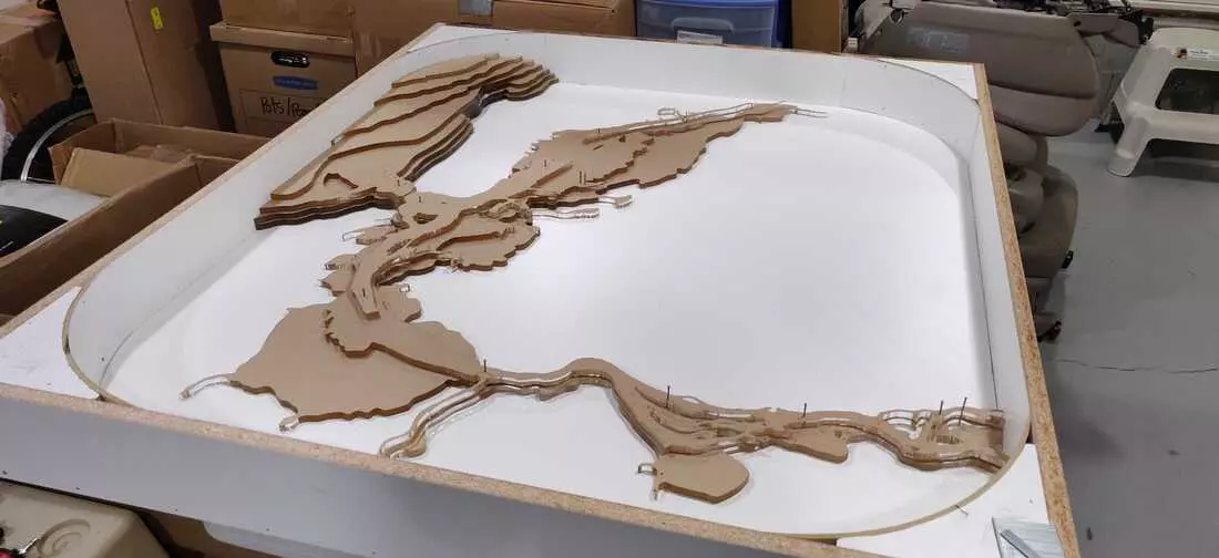
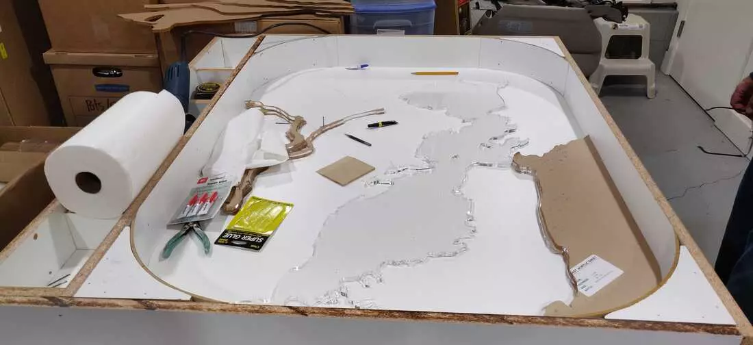
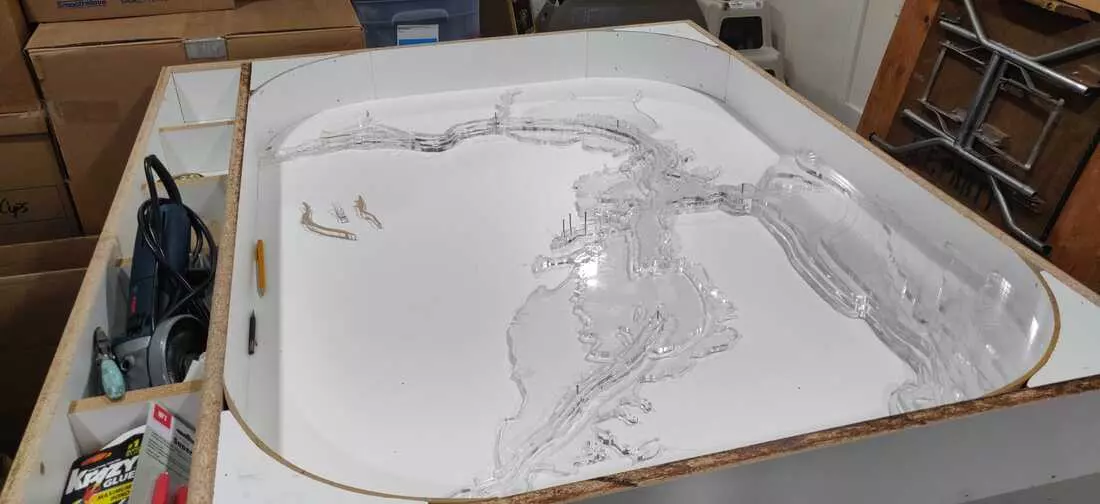
Once the box was complete, the acrylic layers were aligned using pins through the pre-cut alignment holes, and secured together using a tiny bit of super glue. The mold is incredibly secure, but overwhelmingly intricate. This raises concerns around the feasibility of separating the acrylic from the concrete.
Test Pour Went Poorly
January, 2019
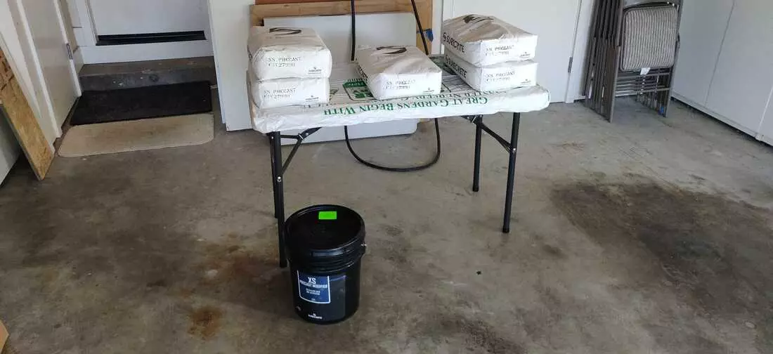
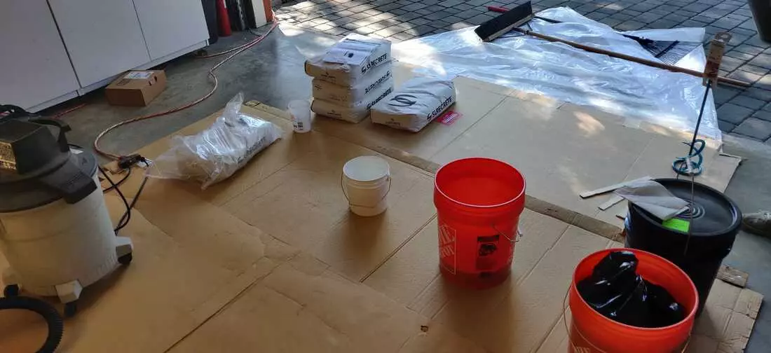
The materials for the concrete pour were acquired. Moving the bags of concrete made me realize this table is going to be HEAVY!
- Surecrete PreCast x 5
- Additive (5 gallon)
- Sealer
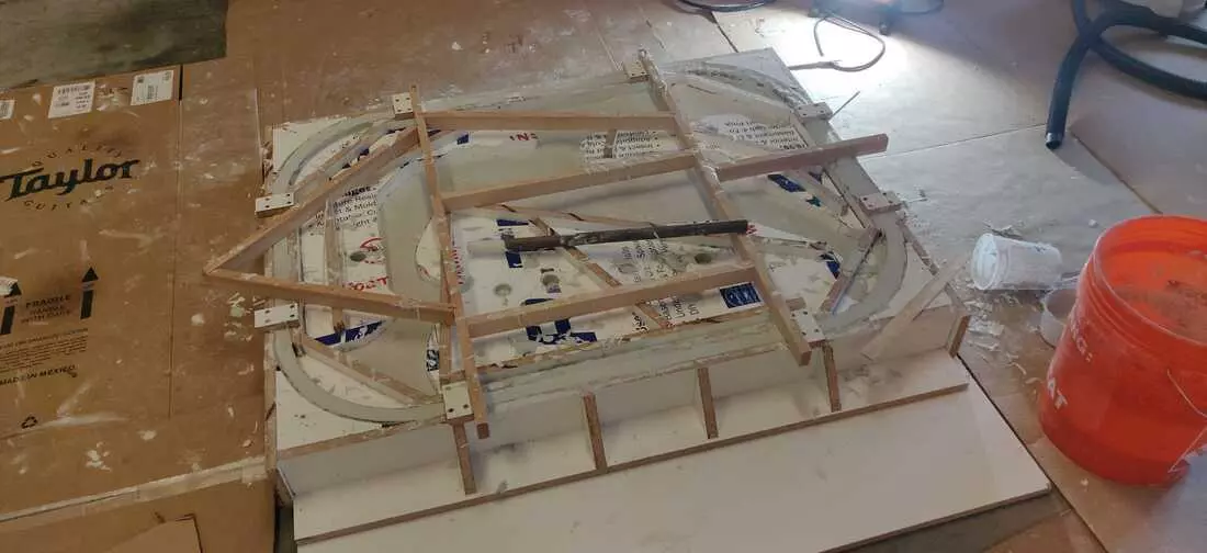
The intricacy of the mold raised concerns about the feasibility of separating the acrylic from the concrete. So I decided to perform a test pour by first creating a small tile with an intricate acrylic inlay. I then masked the MDF board.
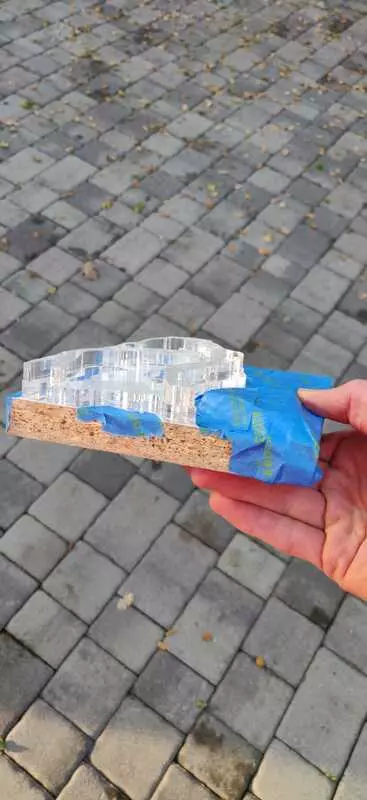
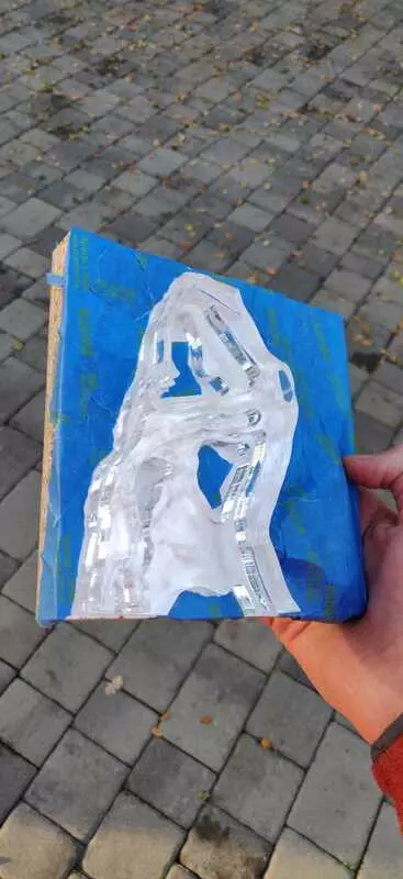
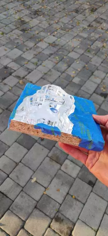
As an extra pre-caution, I added a silicon release barrier over the acrylic (aerosol application).
I finished the mold box and poured the concrete.
Once the concrete dried, the mold was broken apart and it was clear that the acrylic could not be separated without destroying the concrete finish.
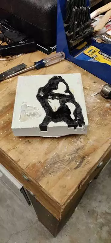
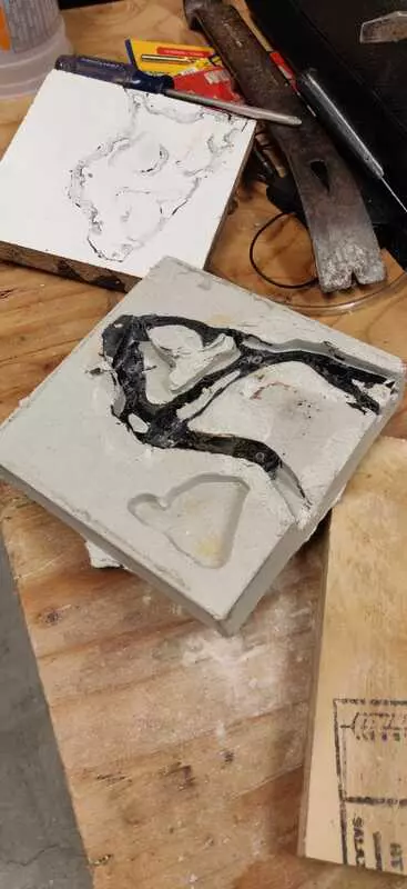
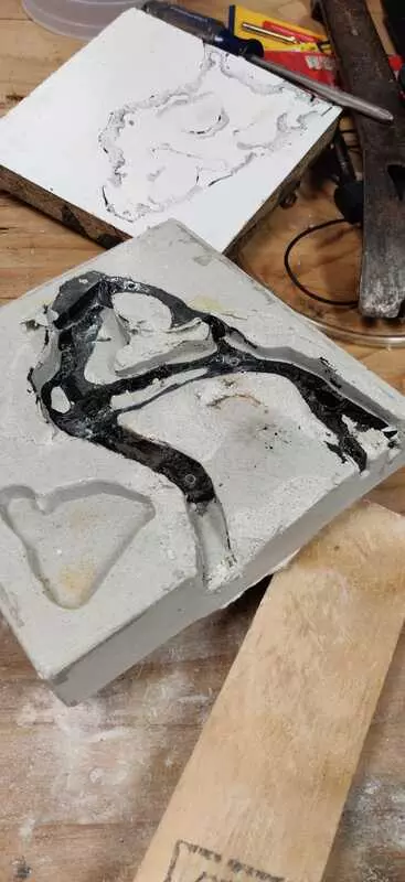
This was incredibly disappointing, but also somewhat expected. I’m just glad to have verified before pouring the entire table. A different strategy is already in motion :)
Breaking the Mold
January, 2019
The new plan is to make a silicone mold of the acrylic and then cast a single piece of resin. That way, concrete can be poured around the resin, which will act as a inlay in the final table.
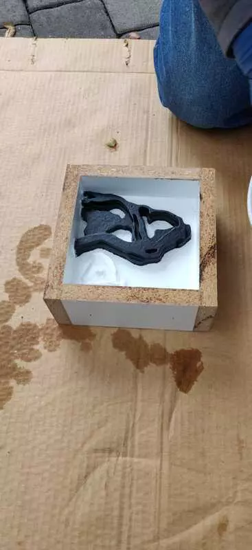
In order to make a mold, the acrylic needed to be exposed for the silicone. Two sides of the MDF box were carefully removed in case re-assembly turned out to be a viable option.
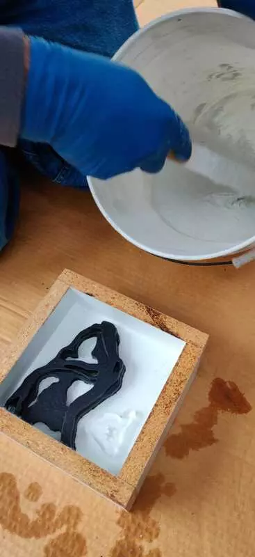
Considering the volume of the mold, a brush on silicone was an inexpensive approach as it saved on material cost. I ended up using a SIlicone rubber material called EZ-Brush from “Smooth On”. The product is meant to create vacuum bag molds and even a thin layer yields an incredibly strong mold. The material was brushed on in 4 layers.
| . | Coat #1 | Coat #2 | Coat #3 | Coat #4 |
|---|---|---|---|---|
| . |  |
 |
 |
 |
| . |  |
 |
 |
 |
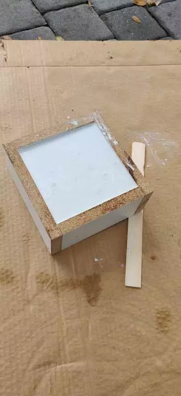
Once the silicone rubber had cured, a thin layer of Smooth On’s Plasti-Paste epoxy was added to created a rigid mother mold.
Working with these products was an absolute treat. I could not be happier with the results and I am sure I’ll approach future projects differently knowing complex molds are this accessible.
When it Rains it Pours
May, 2020
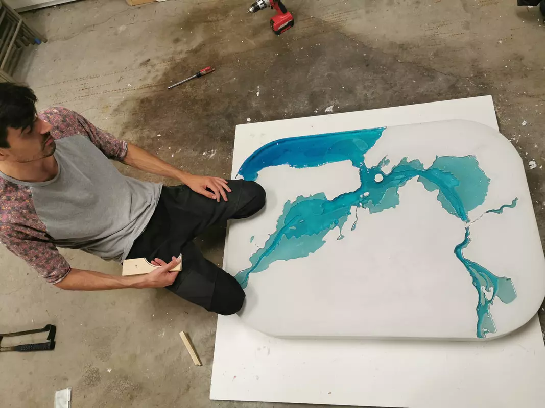
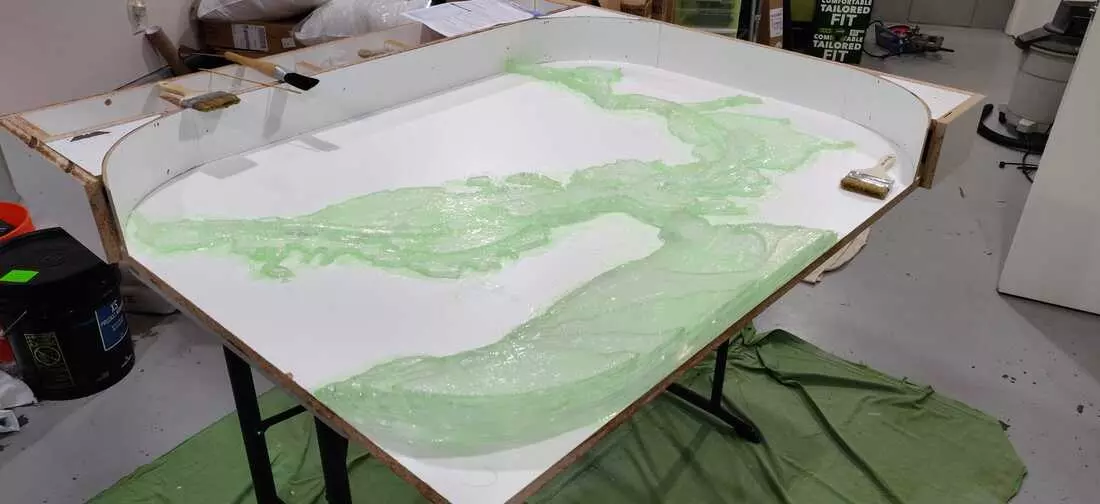
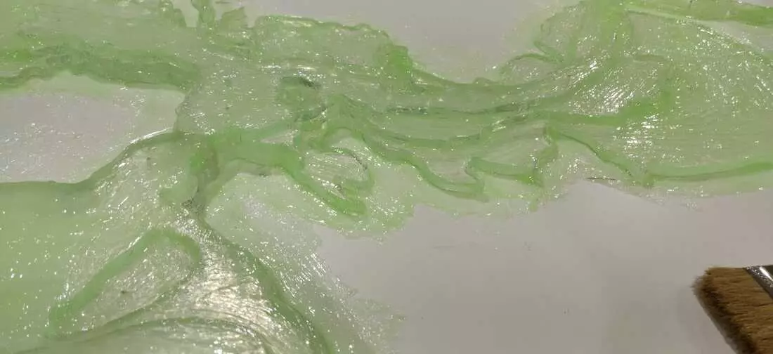
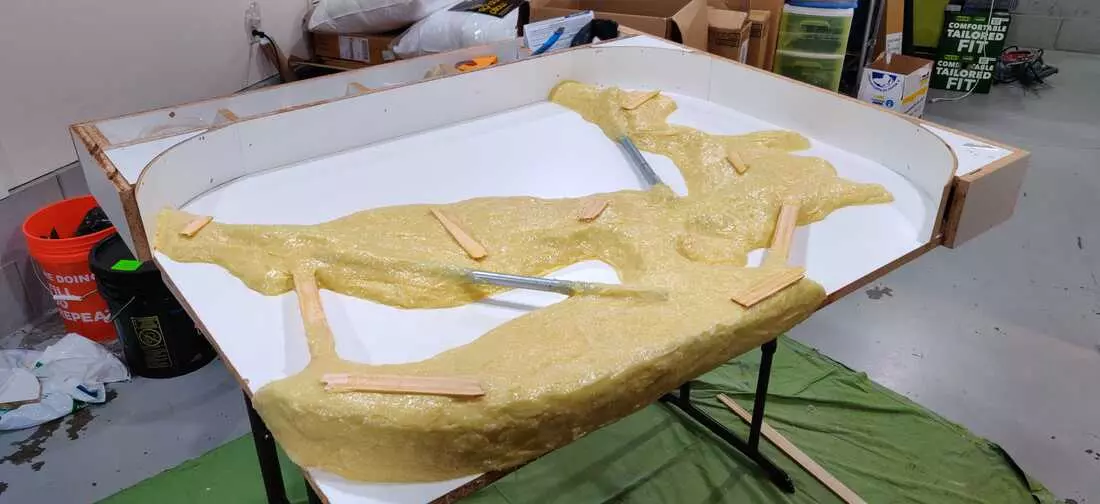
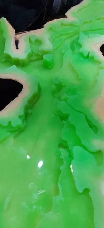
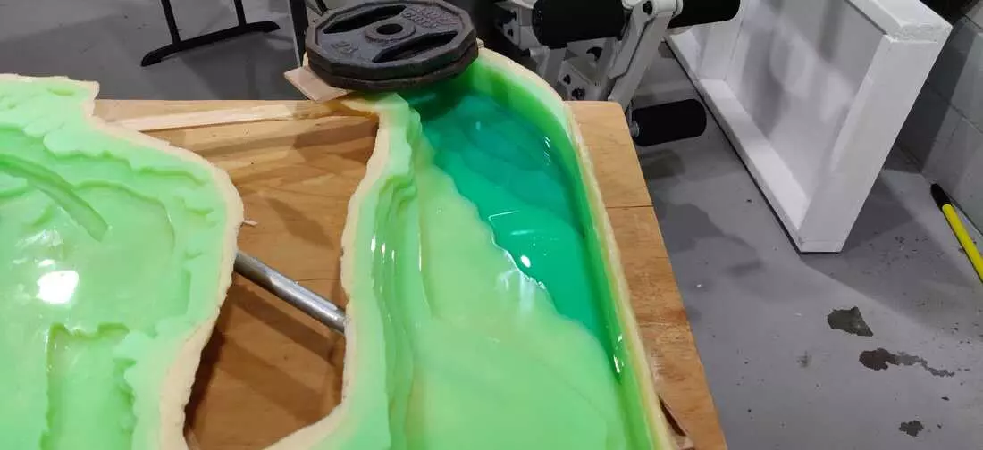
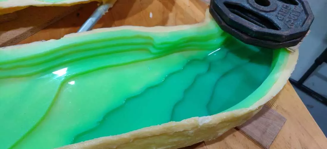
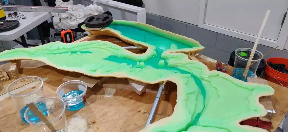
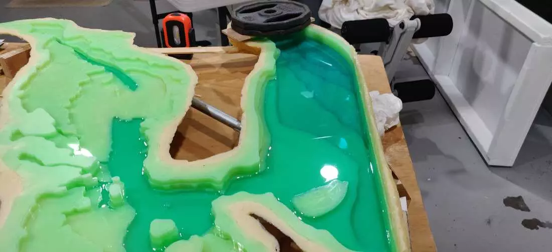
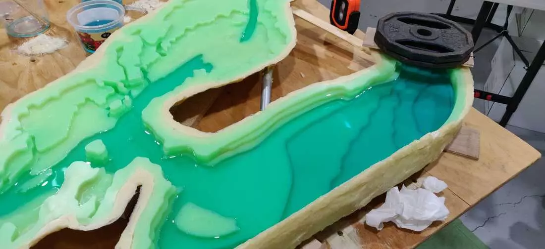
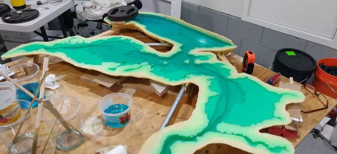
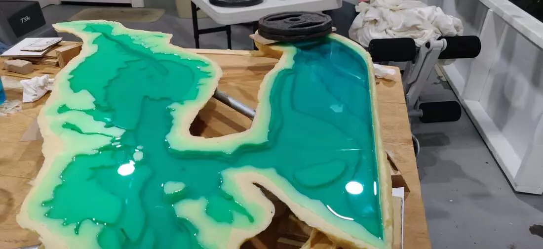
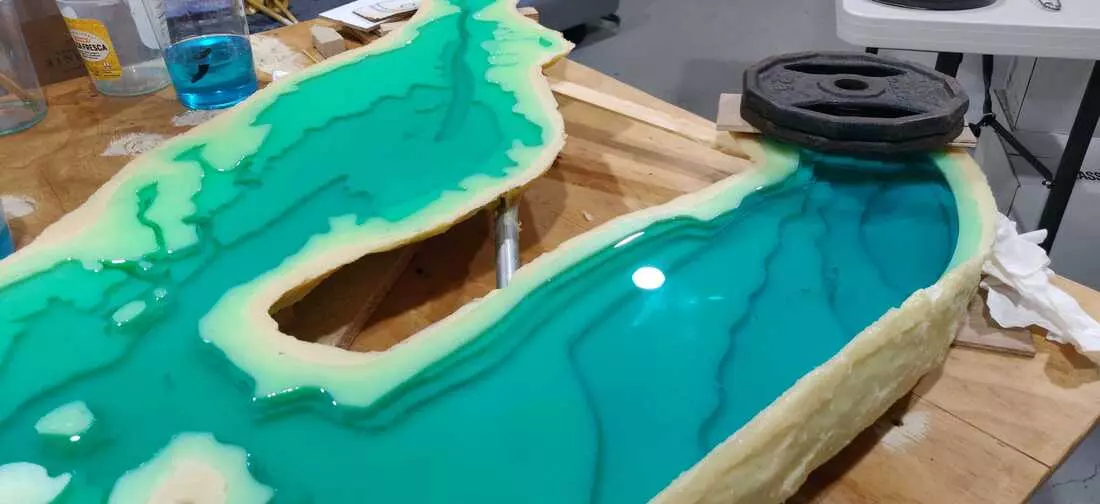
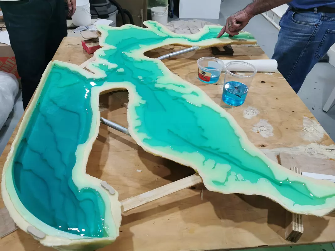
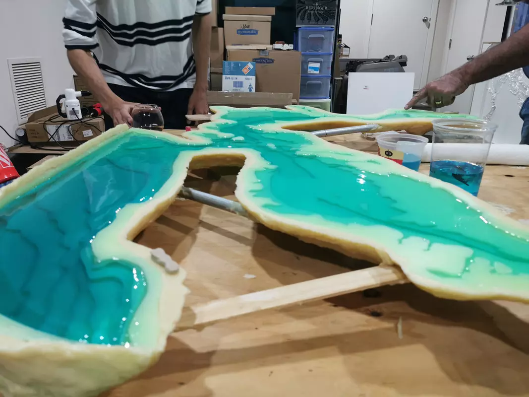
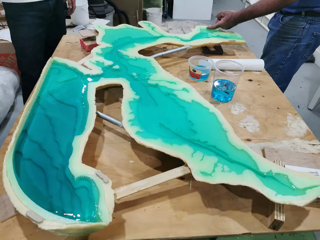
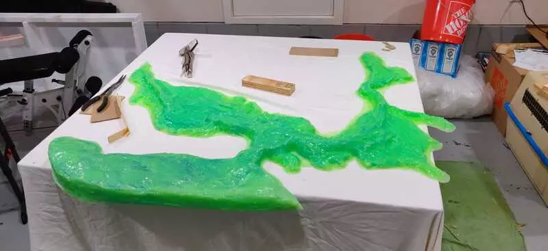
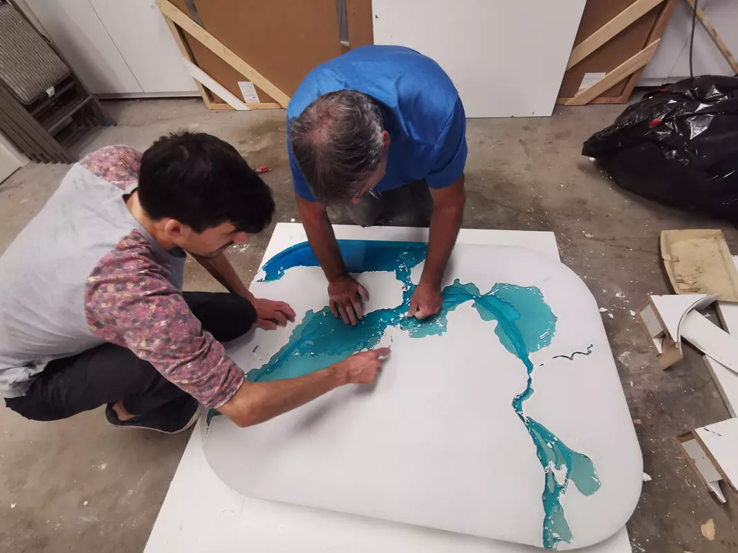
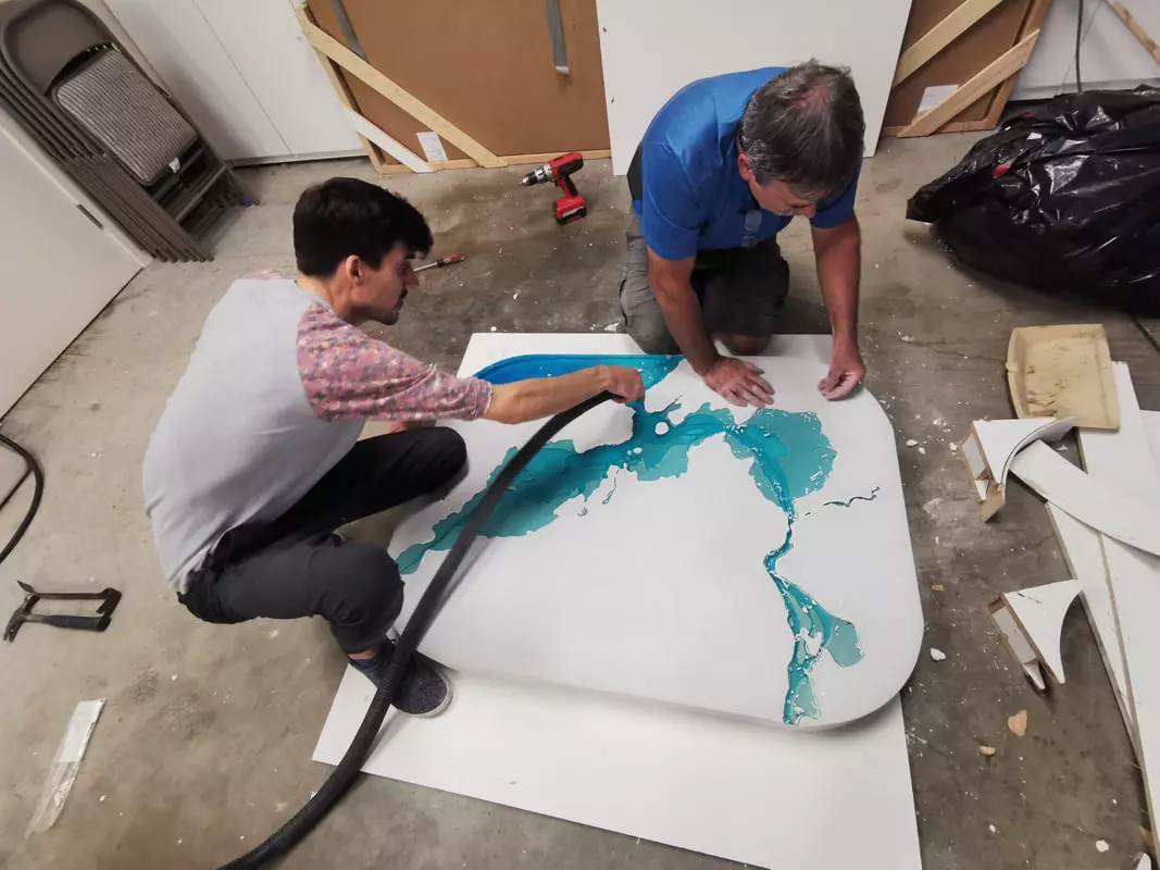
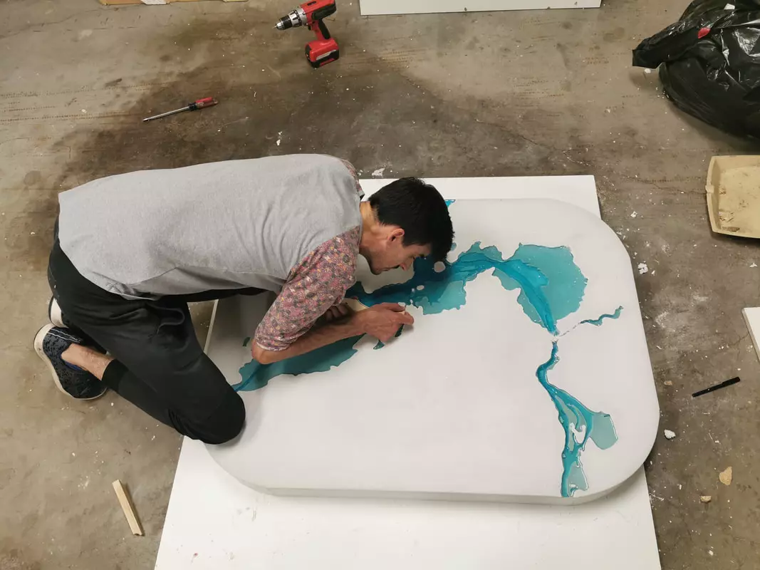
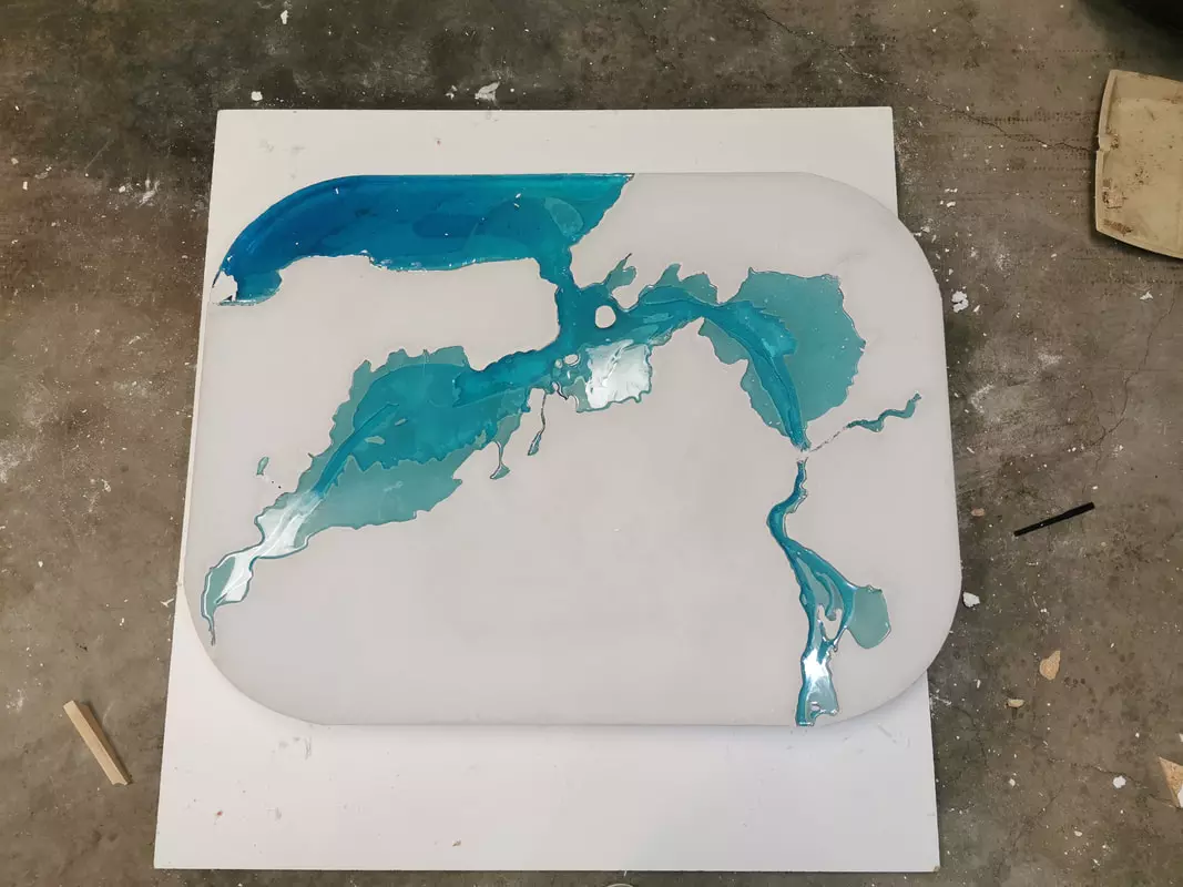
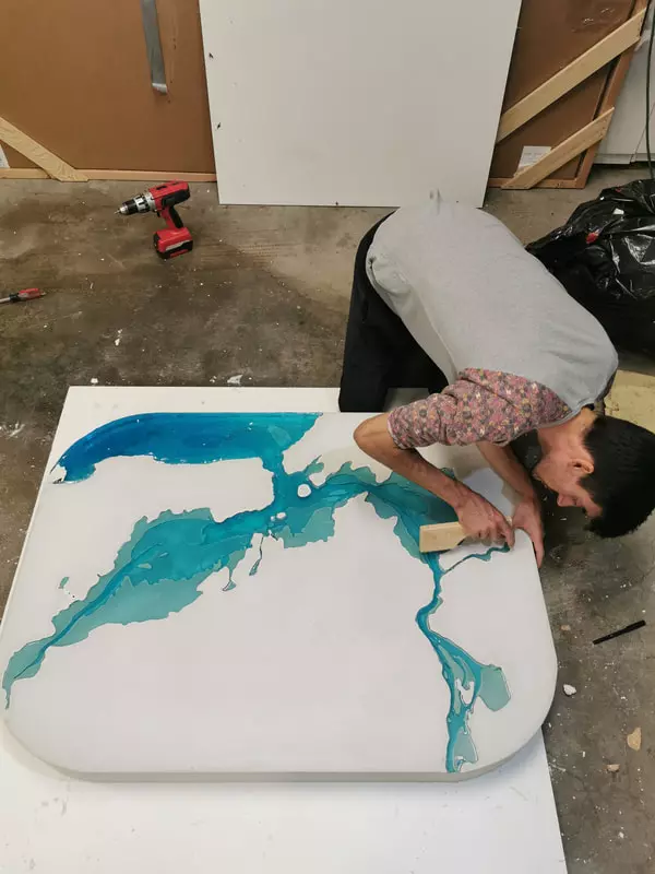
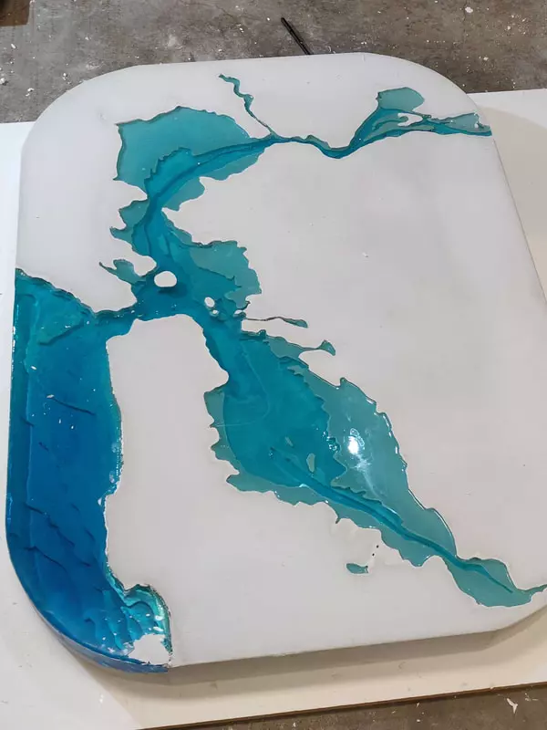
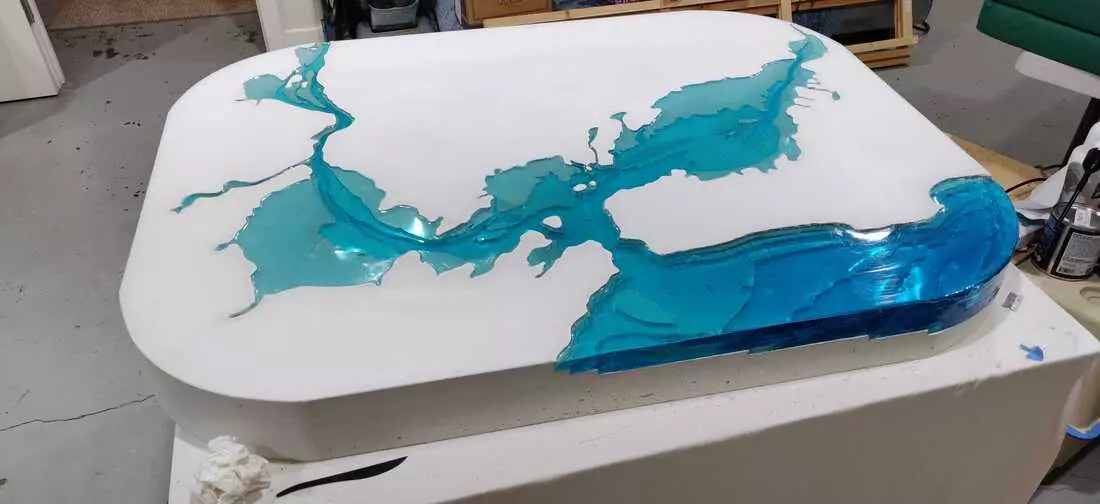
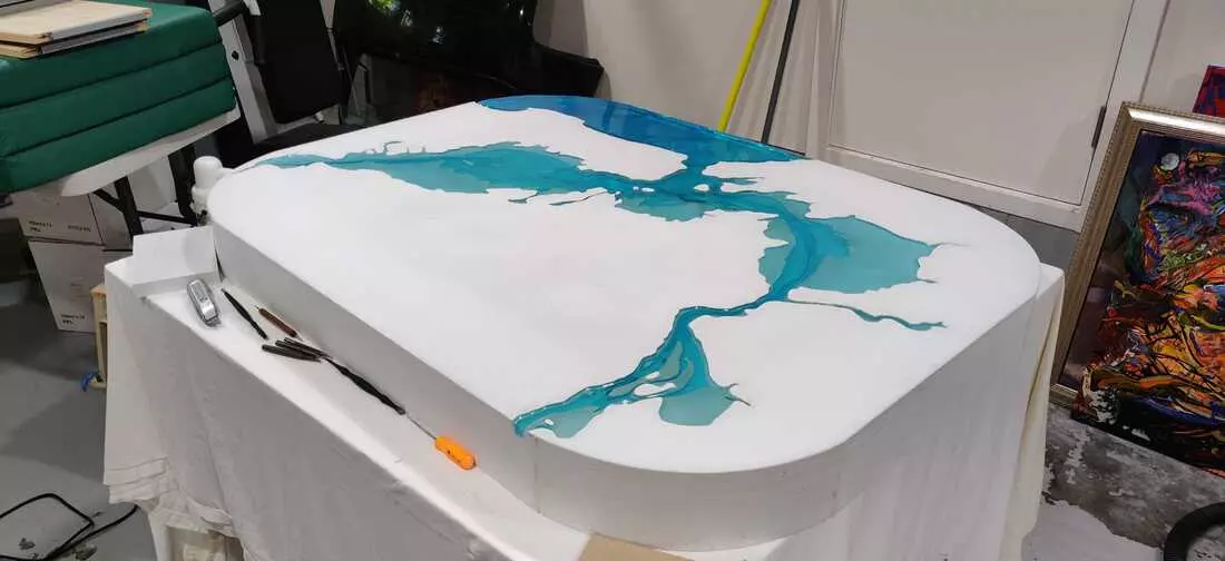
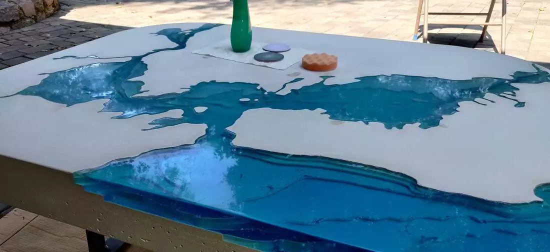
Well… Covid hit, and surprisingly work picked up! While I’m terrifically fortunate to be busy, I all but forgot the table in the early months of 2020. Spring came, and I figured it was time to revisit the project. Eager to see progress, I rushed the pour… resulting in a few bubbles and blemishes I’m choosing to call “features” :)
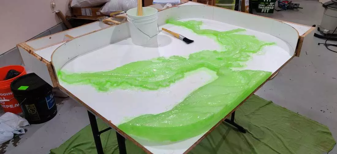
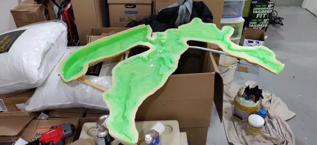
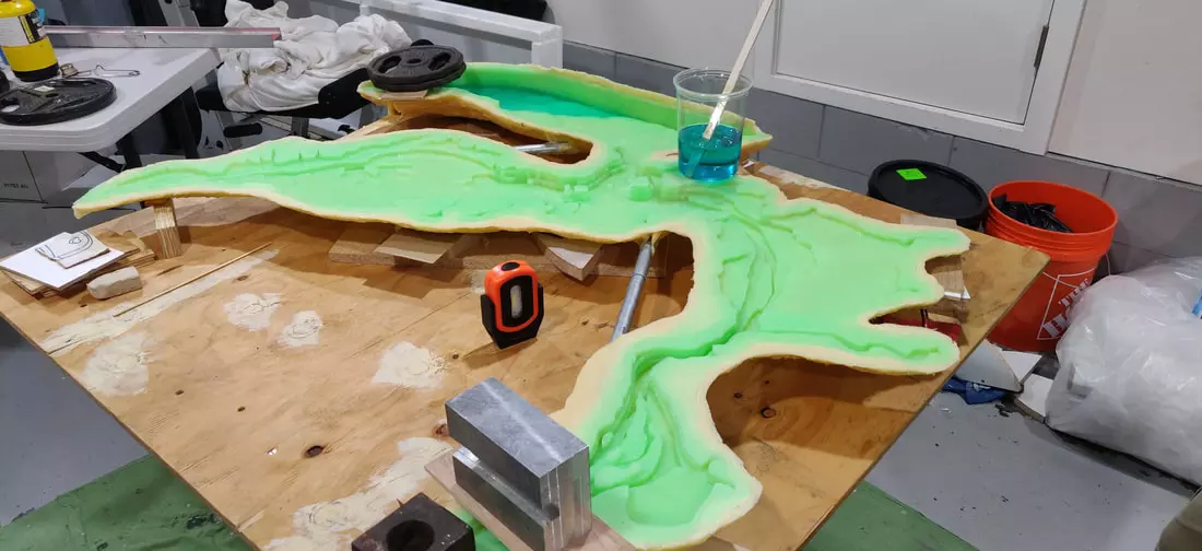
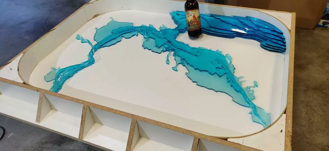
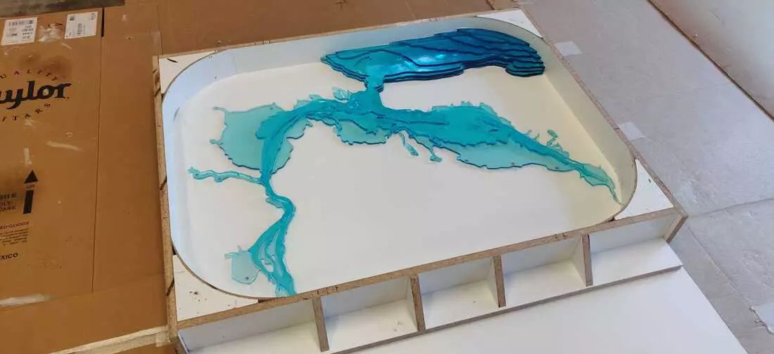
To start the process I leveled the mold in preparation for the pour. This required placing weights on various corners of the mold because it had warped while in storage. The mixing and application of resin was broken into 3 separate pours, each bigger than the last. Volumes for each pour were calculated from the CAD model. I used a simple 2 part resin mix called “NuClear UV resistant Epoxy Resin”. Despite the resin being made for thick pours, the resin cured with blemishes in the deeper sections.
- Pour #1
- Layers: 7, 6, 5
- Volume: 0.65 qt
- Pour #2
- Layers :4, 3
- Volume: 1.84 qt
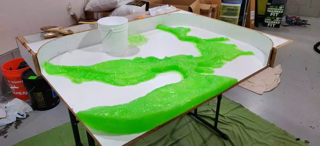
- Pour #3
- Layers 2, 1
- Volume: 5.00 qt
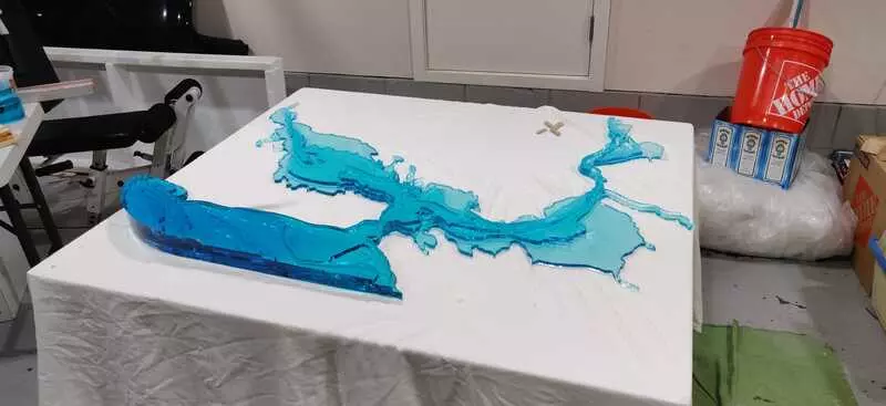
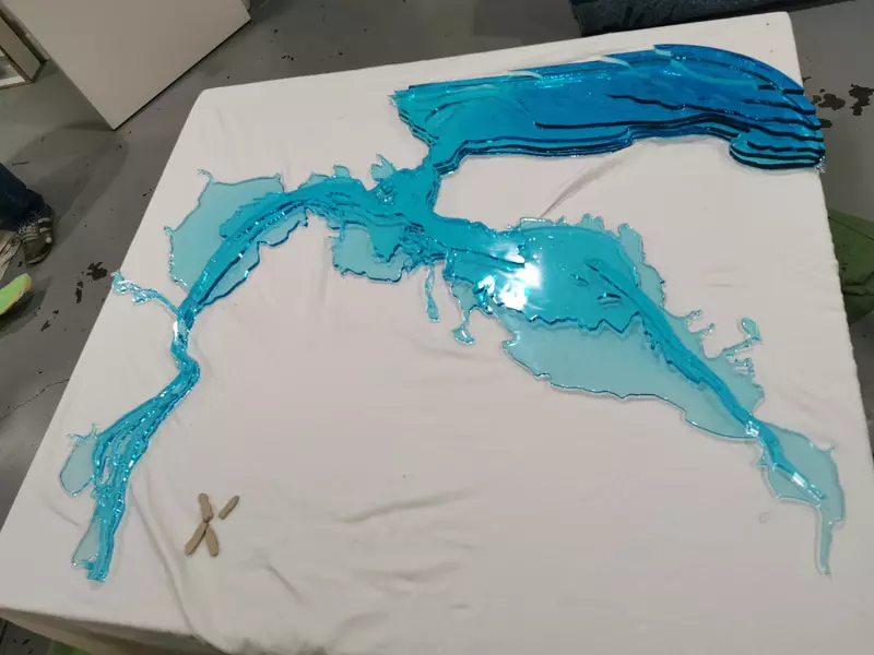
A Roaring Pouring Success
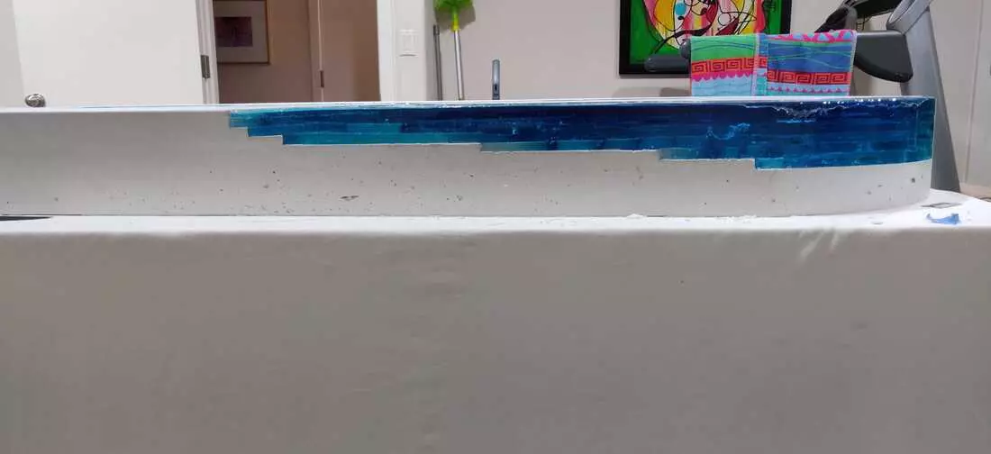
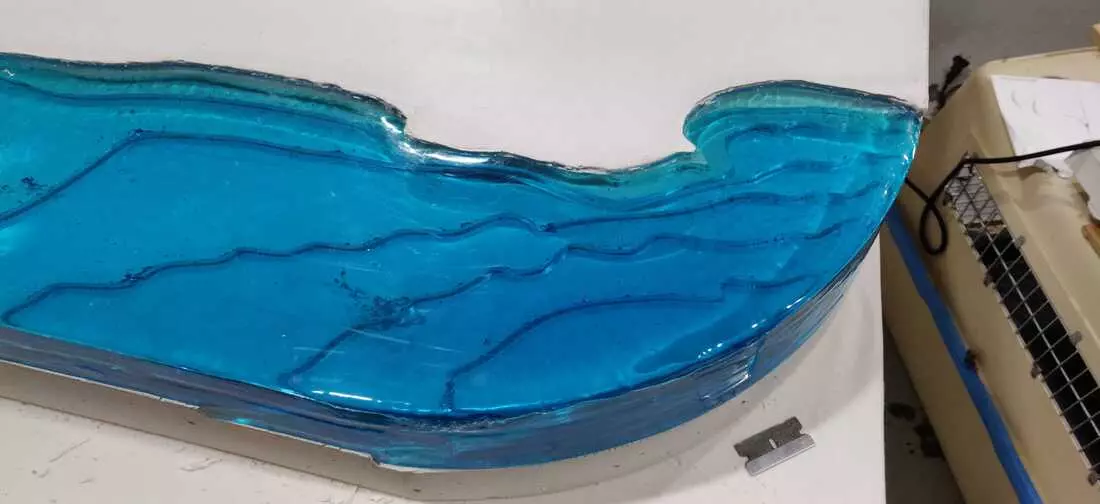
May, 2020
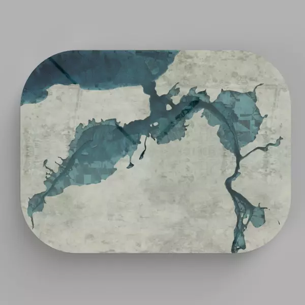
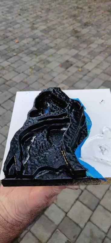
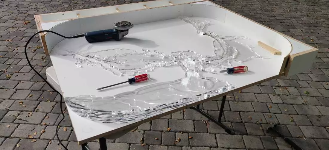
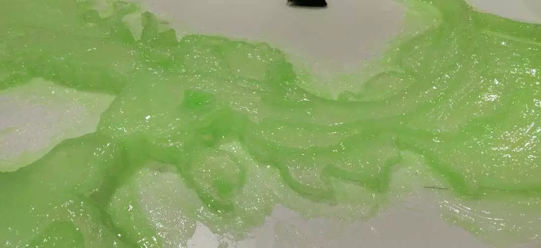
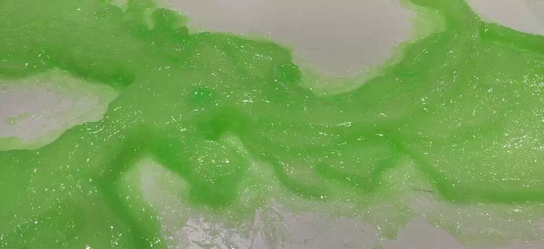
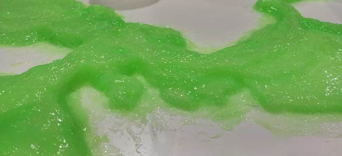
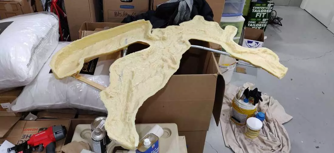
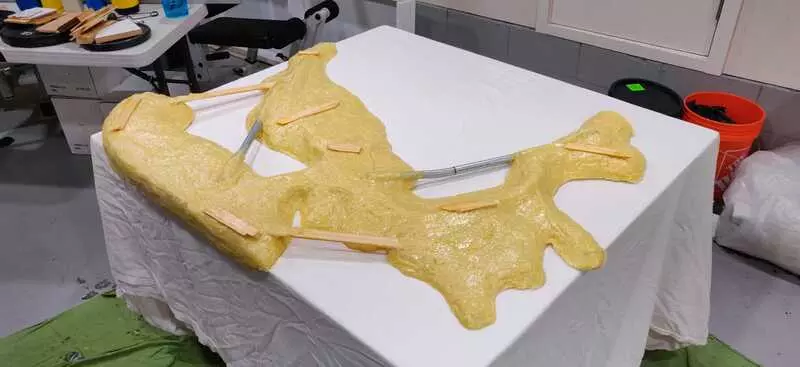
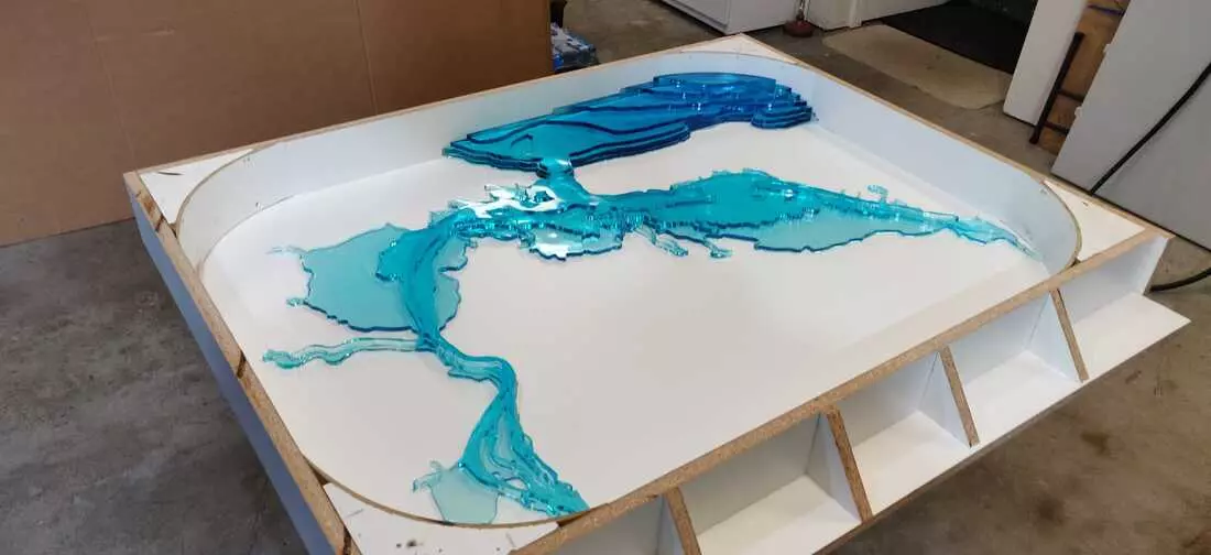
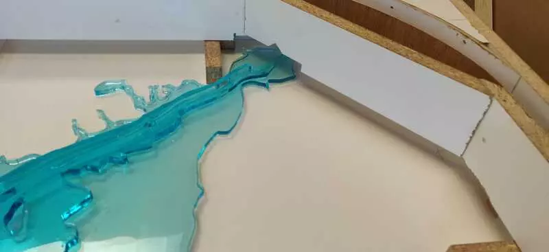
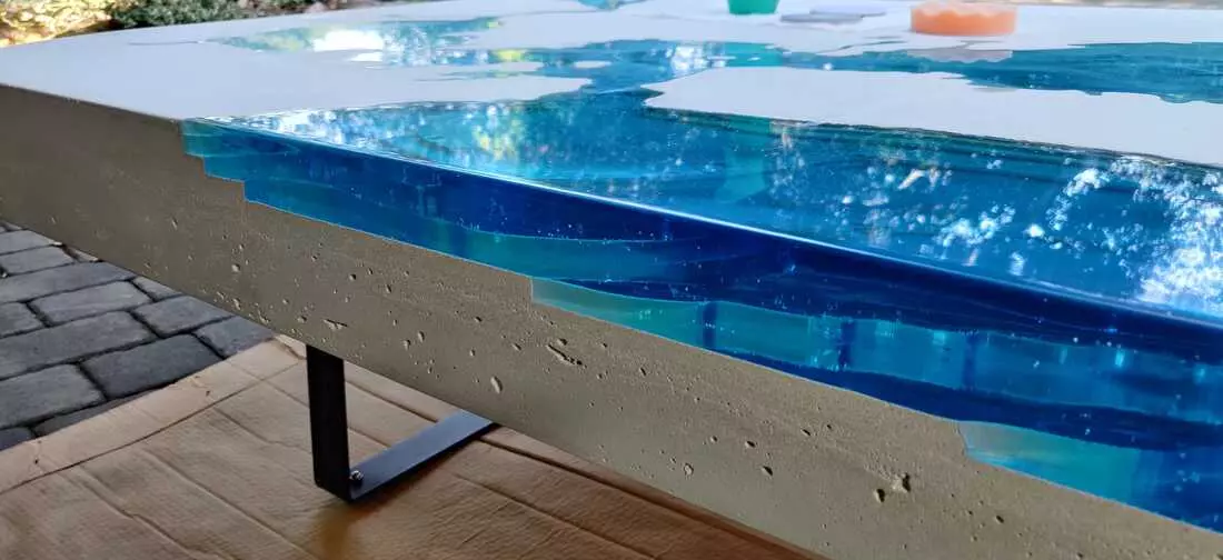
I let the acrylic dry for 2 days, just to be safe. Removing the outer hard shell was difficult around the ocean where the resin overheated and expanded slightly. But once the shell was off, removing the silicone mold was a breeze and INCREDIBLY satisfying. I’m eager to work with this material again. Overall I’m very pleased with how the resin turned out :)
Thinking “inside” Another Box - June 2020
June, 2020
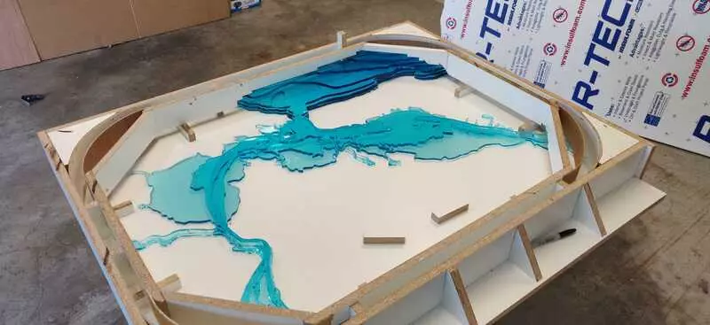
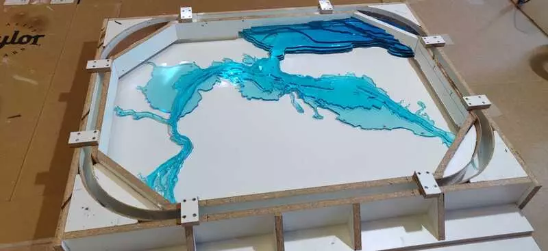
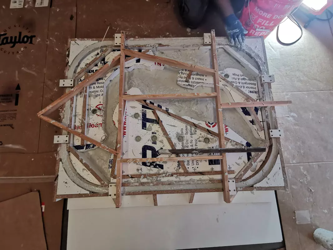
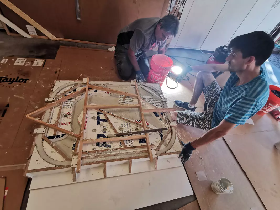
The original MDF box, originally built to house the laser cut acrylic, was destroyed during the intermediate mold. We created a new box for the concrete mold, custom fit to the final acrylic pour.
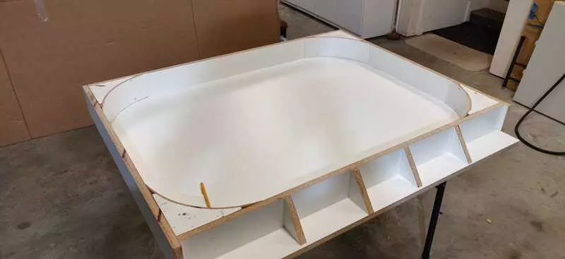
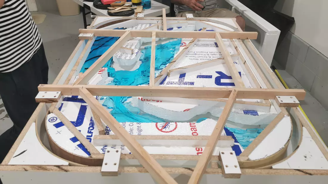
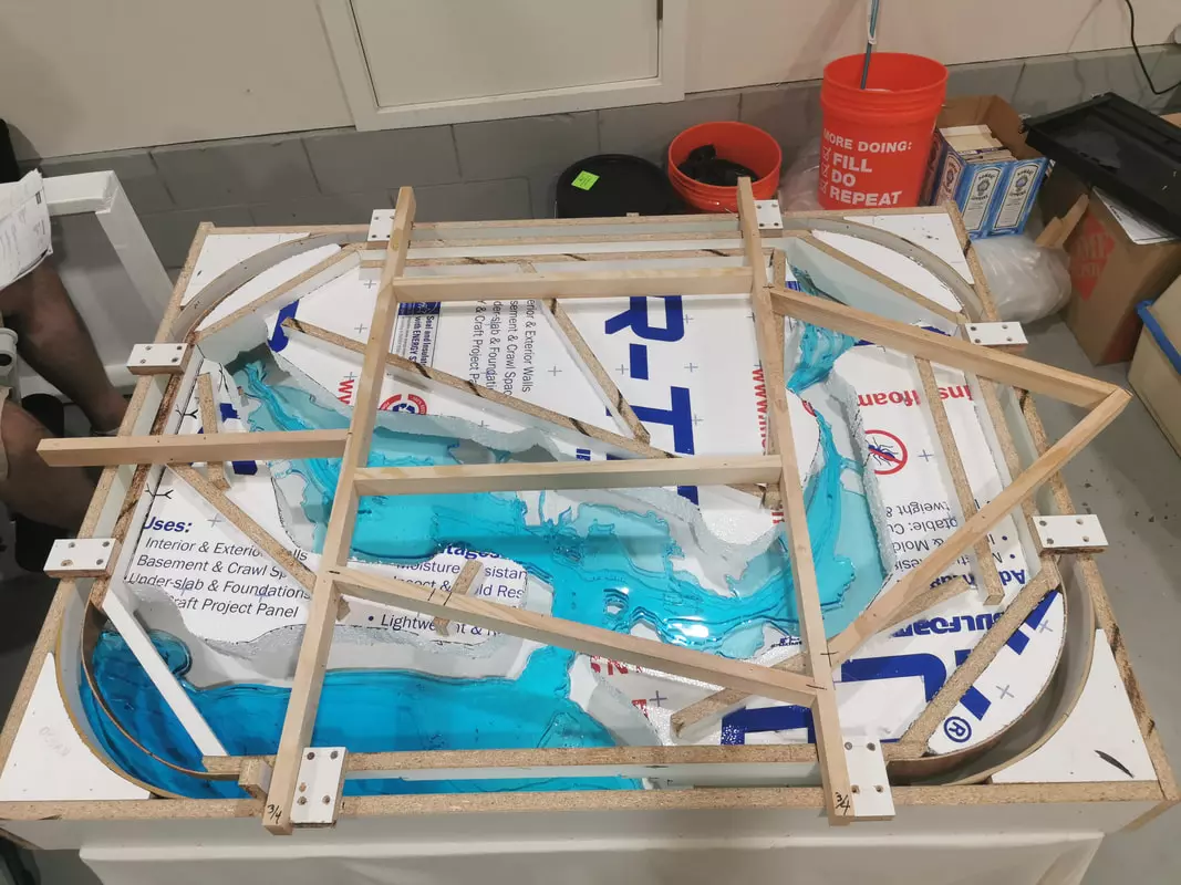
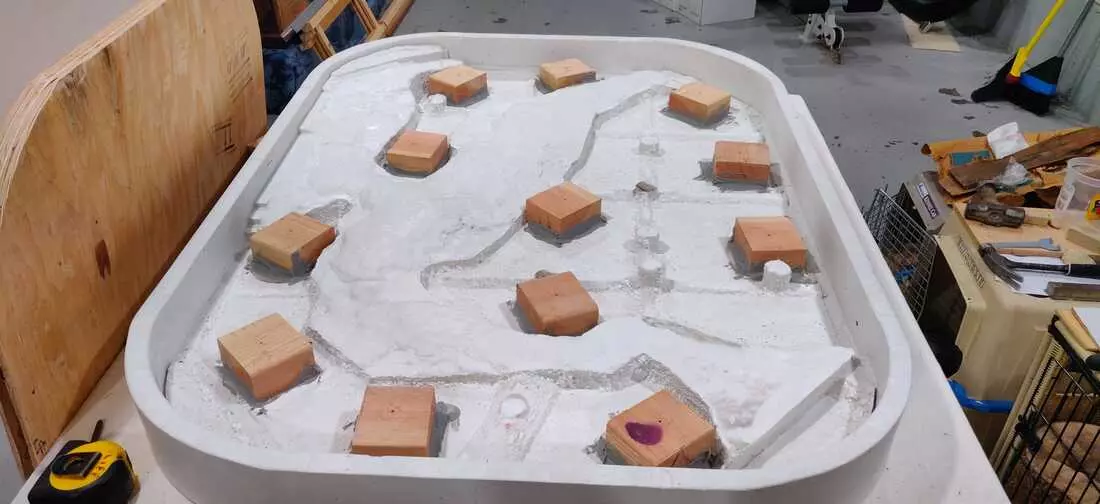
To further simplify the actual pouring of concrete, we also constructed an internal mold that hovers an inch off the surface. This should keep the concrete nicely in the side channels without having to form it by hand.
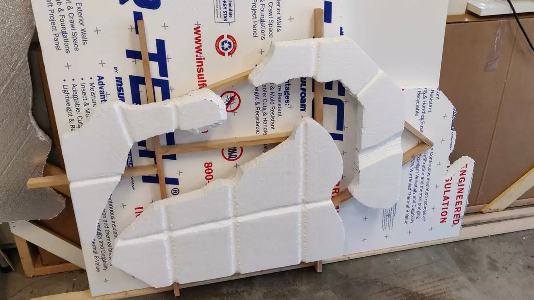
Lastly, we cut some large pieces of Styrofoam to fill larger empty spaces of the mold. This should keep the concrete pour to ~1” thick overtop the complex surface.. hopefully coming in at ~150-200lb instead of ~500lbs that would be required to submerge everything w/ concrete alone. We also cut grooves in the Styrofoam to serve as support channels for extra strength.
Concrete Evidence of Success
July, 2020
We actually poured the concrete. It finally happened!!! The internal mold worked incredibly well!
Taking the mold apart was an all hands affair. My partner Anna managed to snag a timelapse video as well. Everything went smoothly, which made the long mold making process worth it. The table still requires a bit of clean up and detail work… but overall I’m elated with how it turned out!
Finally, a Leg Up
August, 2020
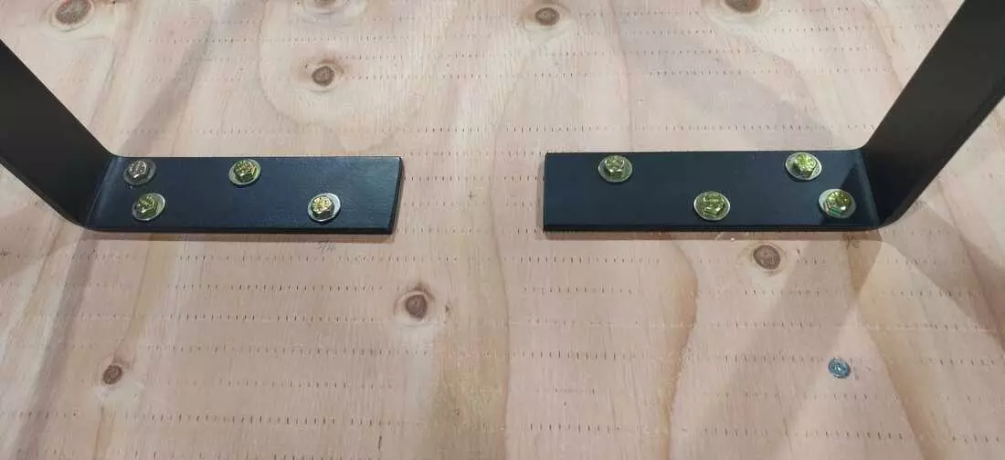
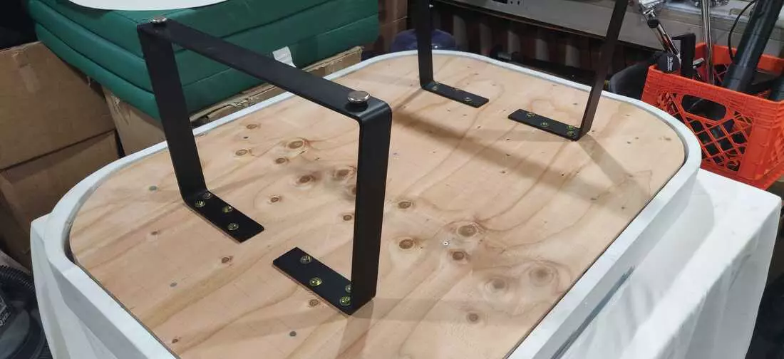
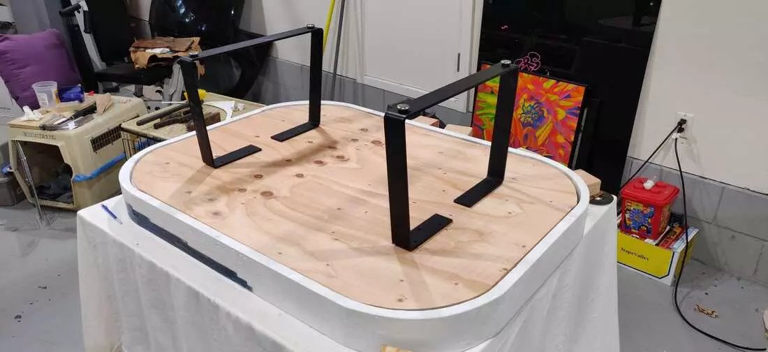
Legs were an afterthought. To mount them in a sturdy fashion, I decided to create a thick inner platform out of 7/8” ply, resting on sanded and leveled risers which were epoxy welded to the concrete. The legs themselves are then mounted to the thick plywood with hardened steel bolts and a decent set of washers/lock nuts. While I didn’t like the mounting of the legs being an afterthought in the design, they’re incredibly strong. The table is a ROCK and moving it has become quite an ordeal :)
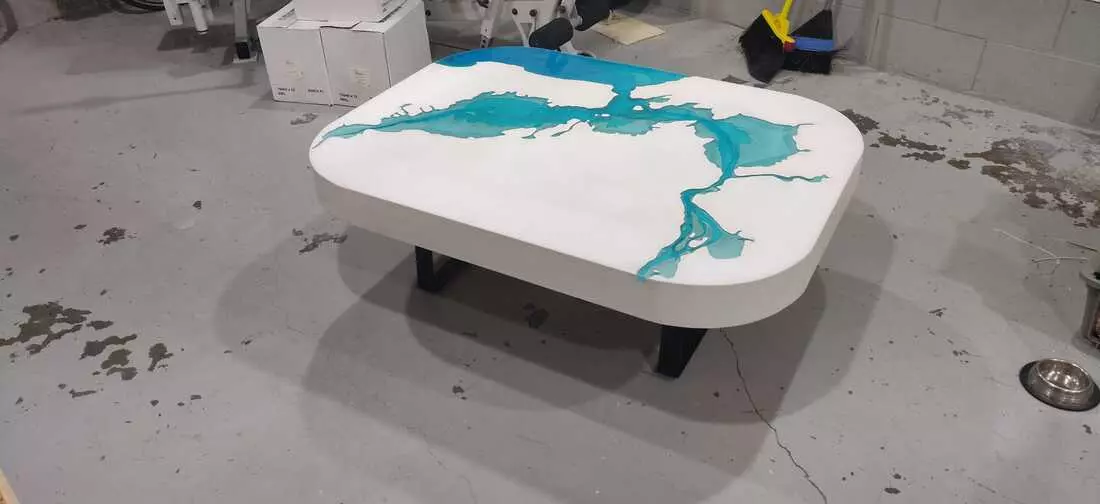
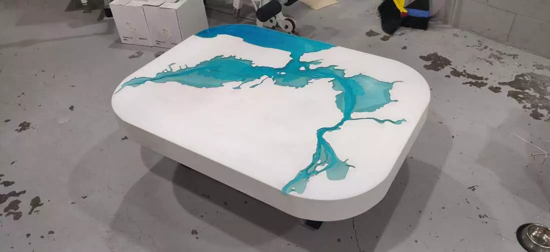
I Couldn’t Think of a “polished” Title
September, 2020
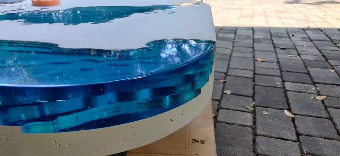
Then came the sanding… and a lot of it. I used a combination of wet and dry sanding in passes spanning 120 to 3000 grit, before a polish to make the acrylic really shine. This process took the better part of a day, and by the end I couldn’t unlock my smart phone as I’d sanded my finger prints off… ha!
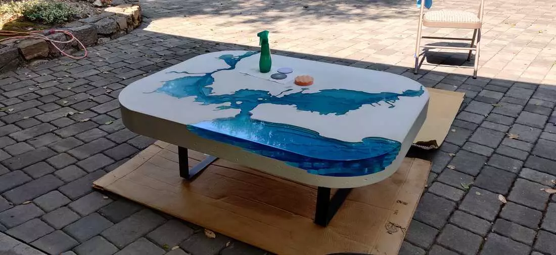
Finally, after sanding and polishing, I sealed the concrete.
Comments